Valve

a valve and valve body technology, applied in the field of valves, can solve the problems of compromising the sterility of the valve, affecting the integrity of the second seal, and difficult to meet acceptable standards, so as to easy to separate the first seal, and reduce the risk of loose particles

Inactive Publication Date: 2010-08-03
GL TOOL & MFG
View PDF19 Cites 2 Cited by
  • Summary
  • Abstract
  • Description
  • Claims
  • Application Information

AI Technical Summary

Benefits of technology

This invention provides a way for quickly separates two parts - called a joint section or fractured zone on a flexible tube used in medical procedures. When this part needs to separate it from another component, there's just enough space inside them to allow easy movement without getting stuck together. By forming these connections along specific areas, the device becomes more reliable because any small things get trapped behind while still being able to open properly.

Problems solved by technology

Technologies described involve improving the reliability and safety of chemicals (chemistry) handling processes involving small vessels containing fluids like water or other liquids. One approach proposed uses a removably secured lid on top of the vessel's closure cap but without affecting its cleanliness level. Another solution proposes using a cylindrical fitting inside the container instead of covering any areas except those covered by the bottom wall of the tank. Additionally, some solutions require specific tools and procedures to ensure proper functioning while maintaining sanitation levels.

Method used


Image

  • Valve
  • Valve
  • Valve

Examples


Embodiment Construction

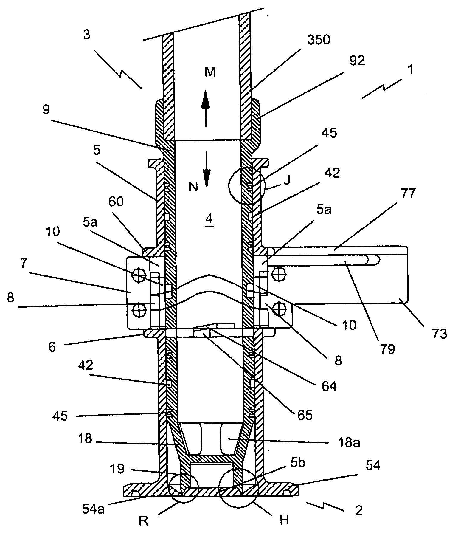
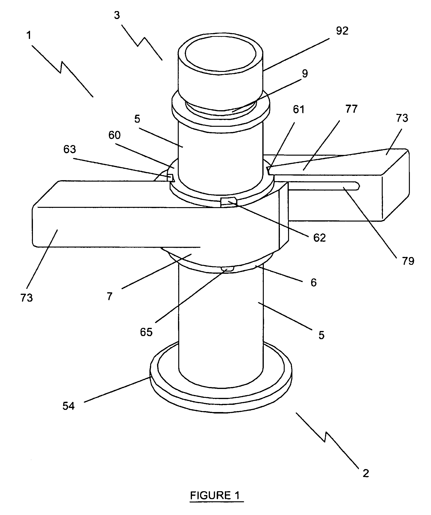
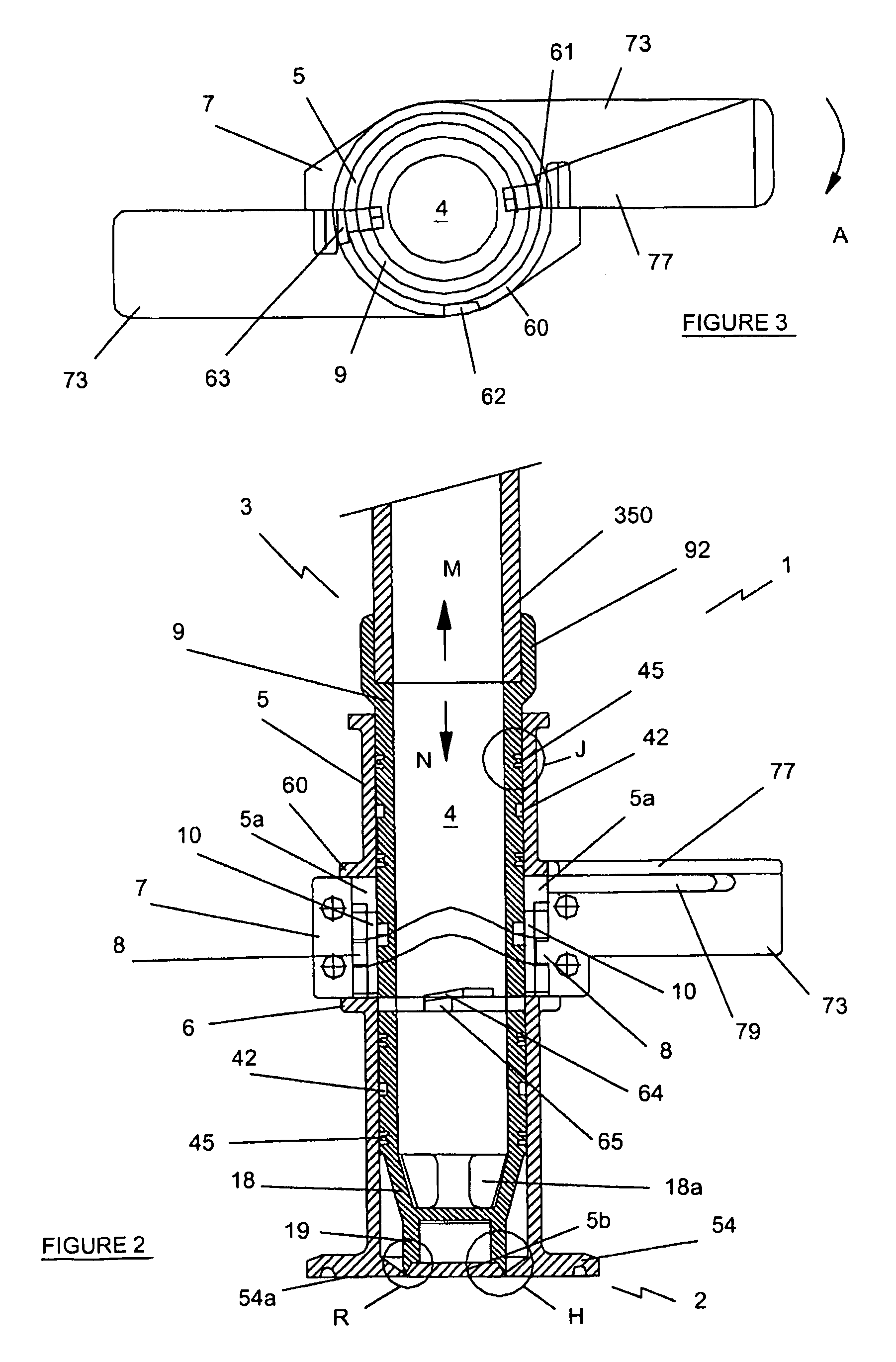
[0115]Referring to the drawings and initially to FIGS. 1 to 3, there is shown a valve indicated generally by the reference numeral 1. The valve 1 has a body having first and second open ends 2, 3 and a passageway 4 extending between the ends 2, 3.

[0116]The body of the valve 1 comprises a hollow tubular housing 5. A hollow tubular piston 9 is disposed within the housing 5. The piston 9 is movable along a longitudinal axis of the housing 5 by an actuator 7 rotatably mounted on the outside of the housing 5 and coupled to the piston 9 via a cam mechanism comprising a cam 8 of the actuator 7 and a pair of cam followers 10 mounted on the exterior of the piston 9. The housing 5, the actuator 7 and the cam mechanism will be described in detail below.

[0117]Referring to FIGS. 4 to 7 the housing 5 is provided by a hollow tube having an internal bore 510. First and second parallel spaced apart guide rails 6 and 60 respectively project laterally from the external surface of the housing 5. The first


PUM


Abstract

A re-closable valve (1, 100, 700, 800) for use in sterile fluid transfer has a body (5) with open entry and exit sides (2, 3) and a passageway (4) for fluid therebetween. The entry side is connectable to an opening of a separate vessel and the exit side is connectable to downstream processing. The entry side includes a first rupturable seal (5b, 500) blocking the opening of the entry side. A piston (9) is connected to an actuator (7) via a cam mechanism (8, 85, 10) which moves the piston (9) axially in the passageway (4) and to the first seal (5b, 500). On movement of the piston (9) during a first actuation, the first seal (5b, 500) is torn free from the entry side to open the valve for fluid transfer. A sharp rim (15) surrounds the opening of the entry side and a curved surface area (193) encircles the piston exterior proximal the entry side. The valve (1, 100, 700, 800) can be re-closed by moving the piston (9) during a subsequent actuation thus engaging the sharp rim (15) with the curved surface area (193) which plastically deform to from a second seal. Arrangements are included to enable the valve (1, 100, 700, 800) to be multiply re-opened and re-closed, if desired.

Description


Claims


Application Information

Patent Timeline
Owner GL TOOL & MFG
Why Eureka
Try Eureka