Method of controlled delivery for use in electrochemical power sources

Active Publication Date: 2012-04-24
UNIV OF SOUTH FLORIDA
View PDF3 Cites 2 Cited by
  • Summary
  • Abstract
  • Description
  • Claims
  • Application Information

AI Technical Summary

Benefits of technology

[0008]In accordance with the present invention, a system that will overcome the deficiencies of the current technology is the use of a control mechanism for the release of chemicals is provided. In on embodiment, this system is based on encapsulating chemicals in liposomes (small vesicles), which are embedded in a polymer matrix made of hydrogel materials. By controlling the hydrogel network structure and the liposomes concentration, it is possible to tune release rates of chemicals to enhance galvanic systems and its energy dosage. In addition, this system has the advantage of being environmentally friendly, as the materials that the packaging technology uses are biodegradable.

Problems solved by technology

However, certain electrochemical power sources use materials that either are not solid or simply do not dissolve in an appropriate manner over time to allow a more precise level of control to improve galvanic reactions.
In this technology, however, it is difficult to control the release of the chemicals, which then lowers the efficiency of the overall power system.

Method used


Image

  • Method of controlled delivery for use in electrochemical power sources
  • Method of controlled delivery for use in electrochemical power sources
  • Method of controlled delivery for use in electrochemical power sources

Examples


Example

[0021]In the following detailed description of the preferred embodiments, reference is made to the accompanying drawings, which form a part hereof, and within which are shown by way of illustration specific embodiments by which the invention may be practiced. It is to be understood that other embodiments may be utilized and structural changes may be made without departing from the scope of the invention.

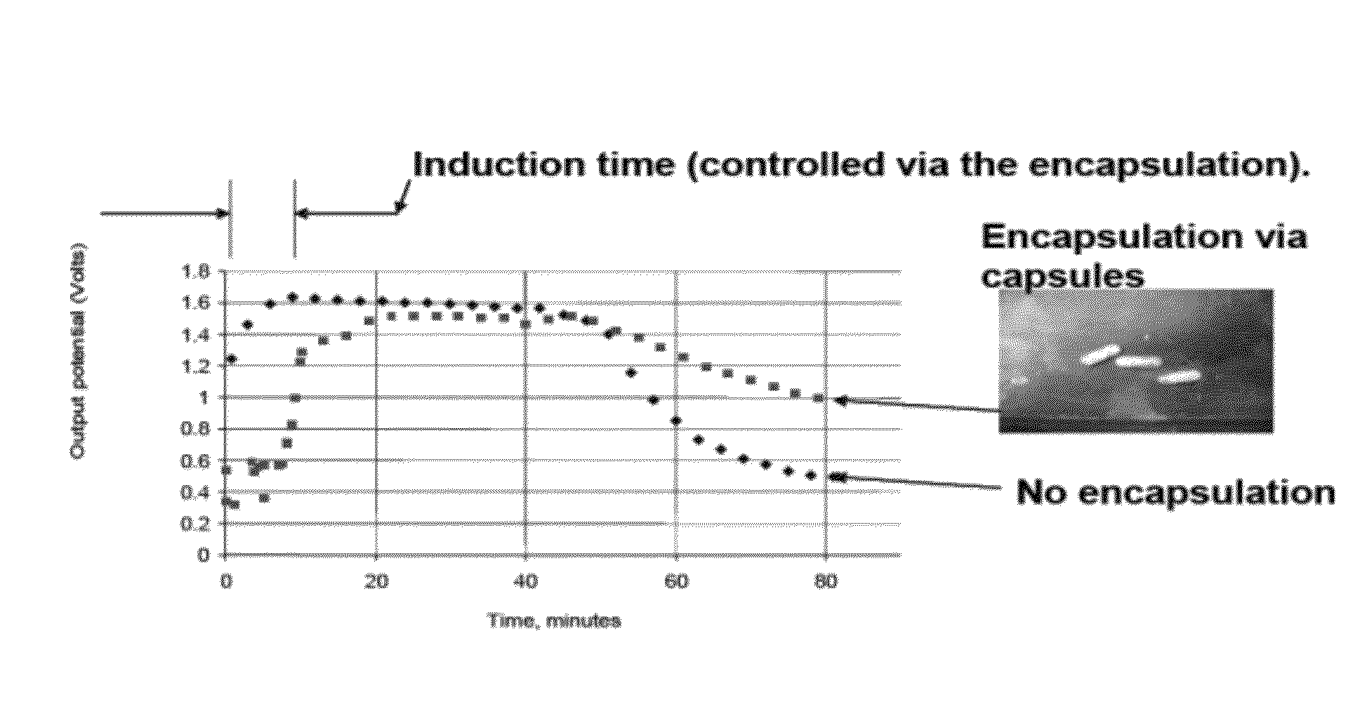
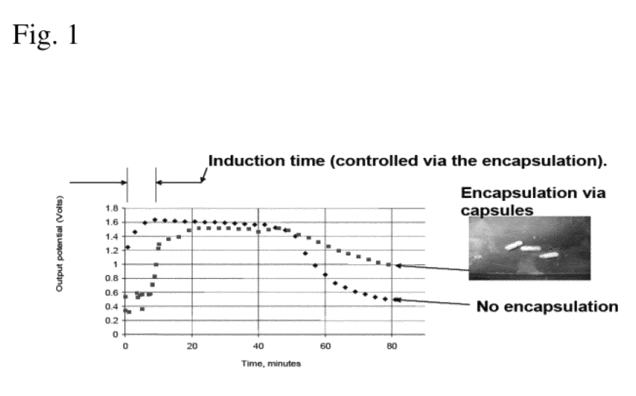
[0022]The present invention provides several embodiments of the invention in which the use of low cost and environmentally friendly materials are used to enhance the power / energy output of several galvanic cells. A first embodiment includes a controlled delivery of a solid chemical in an electrochemical cell. A second embodiment includes a microbial fuel cell with controlled dispersion and release of organic matter from a hydrogen matrix which enhances the power output of the microbial fuel cell. A third embodiment includes the controlled delivery of a reactant into an electrochemical


PUM


Abstract

A system and method for improving electrochemical power sources through the dispensing, encapsulation and dispersion into galvanic chambers of an electrochemical cell. Features of the method include the optimization of the concentration levels of chemicals involved in desired energy producing reactions.

Description


Claims


Application Information

Patent Timeline
Owner UNIV OF SOUTH FLORIDA
Why Eureka
Try Eureka