Flange shear connection for precast concrete structures

Active Publication Date: 2014-08-12
LEK INNOVATIONS
View PDF69 Cites 31 Cited by
  • Summary
  • Abstract
  • Description
  • Claims
  • Application Information

AI Technical Summary

Benefits of technology

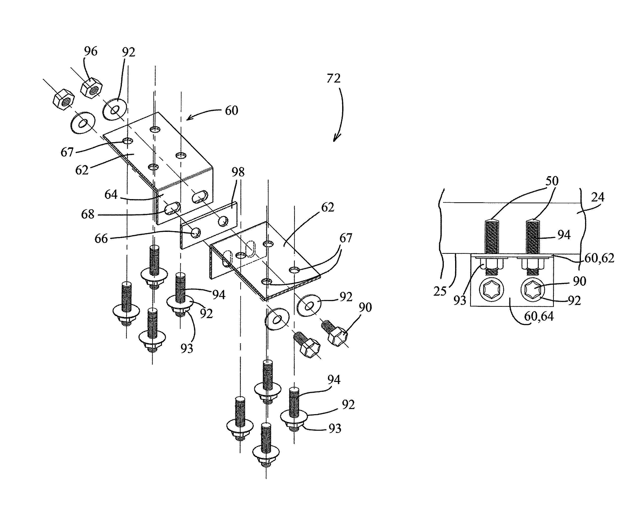
[0029]The flange connector may include a gap between a top surface of the spacer plate and the plane of the horizontal member sufficient to allow the verti

Problems solved by technology

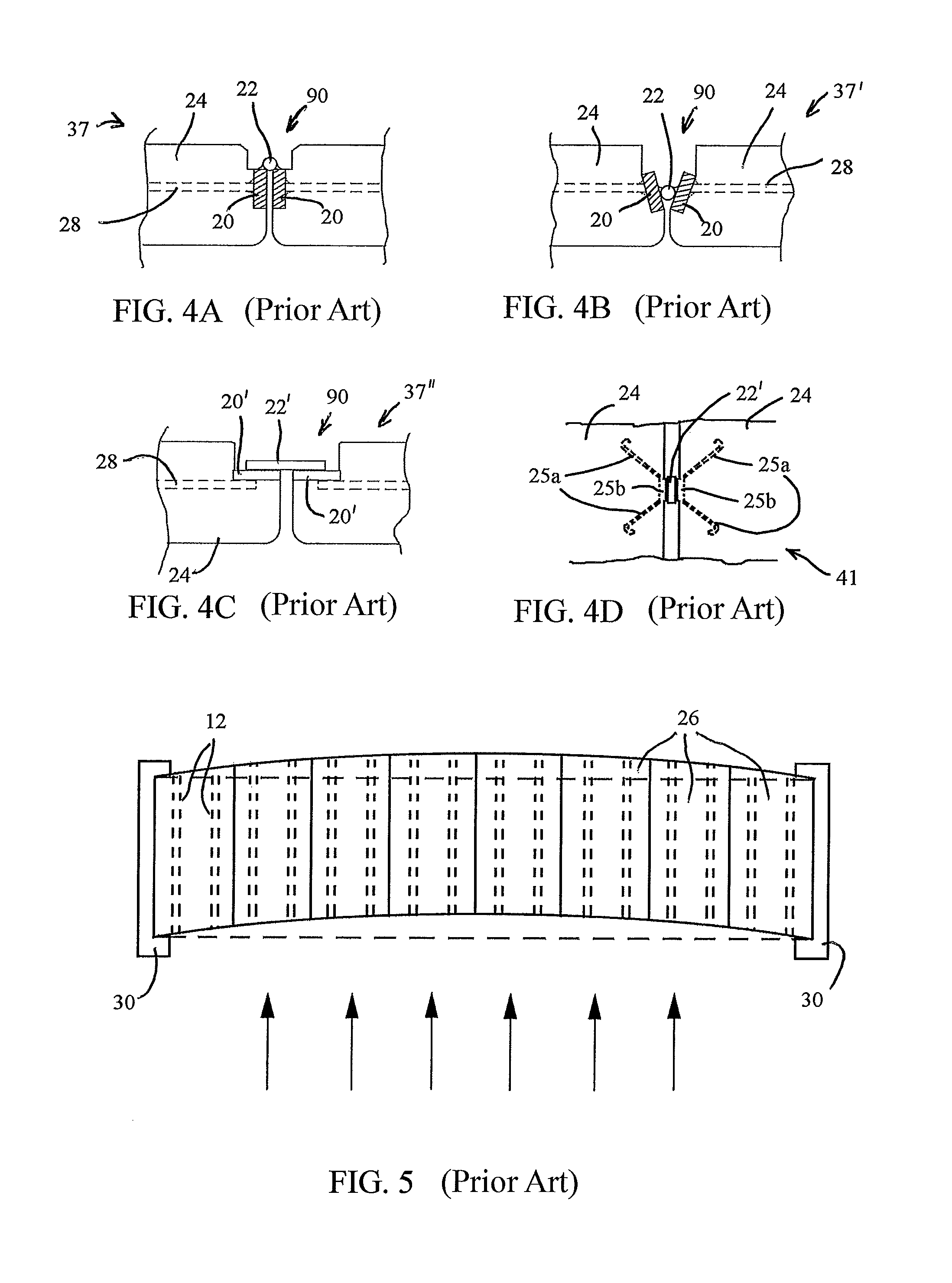
The Vector Connector is not sufficient for tension forces and usually supplements the welded chord connections.
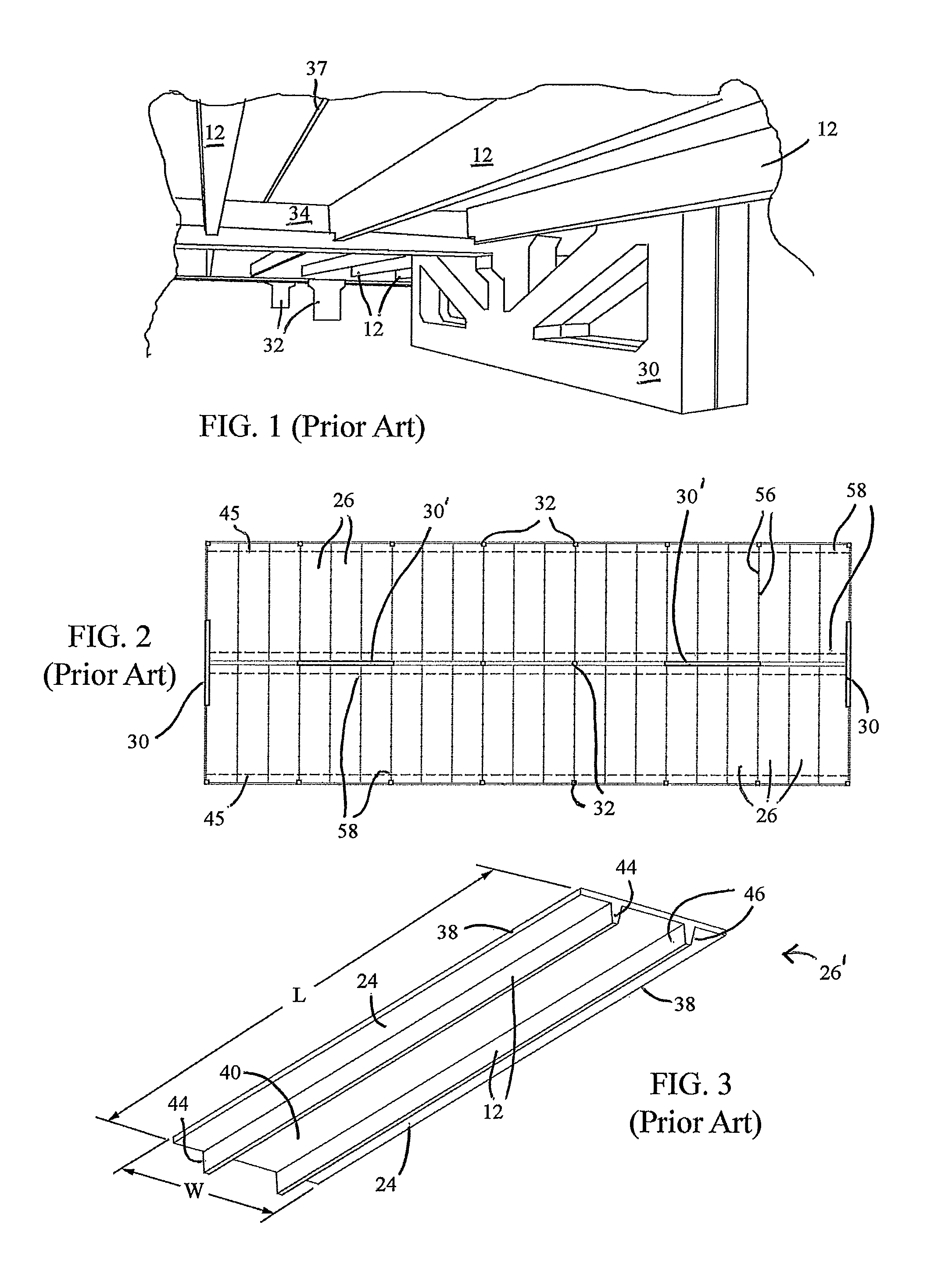
The existing methods of construction produce numerous problems and failures, generally due to poor design, poor fabrication in the shop, poor construction in the field, and in service deterioration.
Welds of the type required require special procedures and specially trained welders and welding code provisions do not allow welds to be used in the manner in which they are loaded in this connection.
This quality control is difficult and costly to perform during fabrication and erection and in service.
When the embedded plates are welded during erection of the concrete structure, the heat of welding causes expansion of the plates causing cracks to form in the concrete.
Road salts deposited at or near the connection then cause deterioration due to corrosion, especially in cold climates where high concentrations of salt is used to reduce or prevent ice formation.
Additionally, the cracks in the concrete allow water to enter, creating further concrete deterioration when the water does freeze.
To slow the progress of corrosion at these conne

Method used


Image

  • Flange shear connection for precast concrete structures
  • Flange shear connection for precast concrete structures
  • Flange shear connection for precast concrete structures

Examples


Embodiment Construction

[0058]In describing the preferred embodiment of the present invention, reference will be made herein to FIGS. 6-24 of the drawings in which like numerals refer to like features of the invention.

[0059]The present invention is an apparatus and a system for creating, replacing, restoring or reinforcing flange connections of adjacent precast concrete structures such as a double tee beam. The system includes providing flexible shear connections along the flanges of adjacent concrete structures. The shear connection is for securing the tee beams from shear forces which shift one beam vertically from the adjacent beam due to gravity loads or longitudinally due to lateral forces such as seismic and wind loads.

[0060]The concrete structure 8 shown in the top elevational view of FIG. 6 includes flexible shear connections 56 along adjacent flanges 24 of precast concrete members 26. The concrete structure 8 is preferably a parking garage and includes at least one diaphragm 6a, 6b which comprises a


PUM


Abstract

A flange connection system for a concrete structure comprising a plurality of adjacent precast concrete members including a platform having a center panel and a first and second flange extending outward from the center panel in opposing directions. The system includes a first and second bent plate each having a horizontal member attached to the bottom surface of the adjacent flanges and a vertical member perpendicular to the horizontal member. The system includes a spacer plate extending in a vertical direction from about a lower edge of the first vertical member to below the first horizontal member and secured between the vertical members of the first and second bent plate with a plurality of fasteners. The first and second vertical member may flex at an upper portion allowing adjacent flange ends to move relative to one another.

Description


Claims


Application Information

Patent Timeline
Owner LEK INNOVATIONS
Why Eureka
Try Eureka