Multi-user digital laser imaging system

a laser imaging system and multi-user technology, applied in the field of medical laser imaging systems, can solve the problems of only being able to exercise a limited degree of control over the overall imaging system transfer function, and unable to account for drift in the overall system transfer function, so as to achieve the effect of minimizing differences

Inactive Publication Date: 2003-02-25
CARESTREAM HEALTH INC
View PDF22 Cites 5 Cited by
  • Summary
  • Abstract
  • Description
  • Claims
  • Application Information

AI Technical Summary

Benefits of technology

This patented technology allows users to create personalized films based upon factors like resolution or sharpness that they want without having to worry about how much toners used actually make them look good over time. It uses a special device called a laser printer (LPR) which controls the amount of light transmitted from a lamp bulb onto photosensitive material before it reaches its final destination. By measuring this quantity and comparing it against expectant results, computer programs automatically generate corrections to improve the quality of printed images. Additionally, LPR devices allow users to set up parameters tailored specifically to individual needs. Overall, this technology improves efficiency and accuracy in producing high-quality prints while reducing costs.

Problems solved by technology

LSM Las Imaging System: Current methods involve manual selection of look up tables based upon experimentation and testing techniques, but they cannot handle changes due to environmental effects like developers' chemistry level change during manufacturing process. Additionally, current method does not take into consideration differences across various sensor settings affecting how well the resulting photosensitive output matches those expected conditions.

Method used


Image

  • Multi-user digital laser imaging system
  • Multi-user digital laser imaging system
  • Multi-user digital laser imaging system

Examples


Embodiment Construction

System Overview

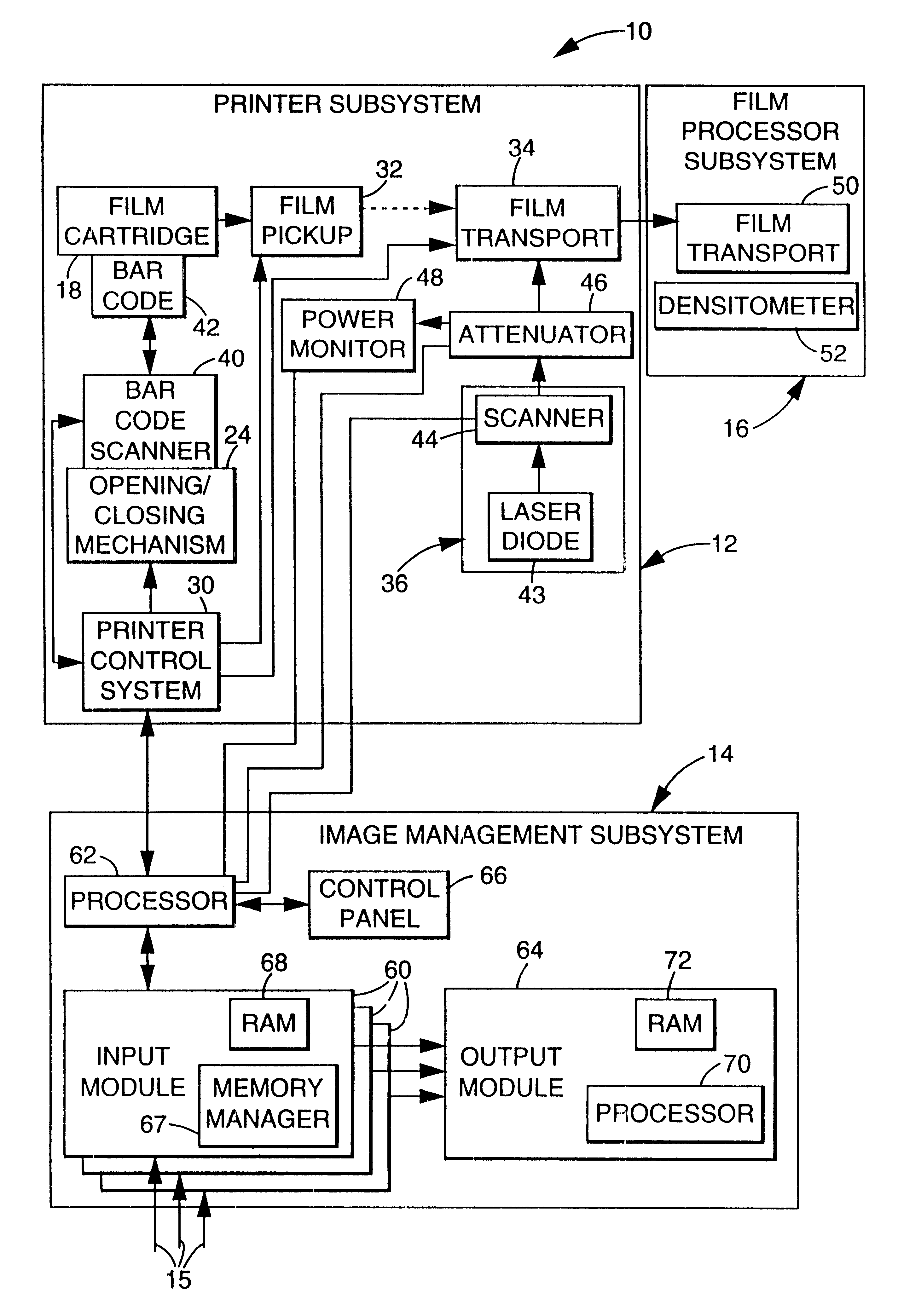
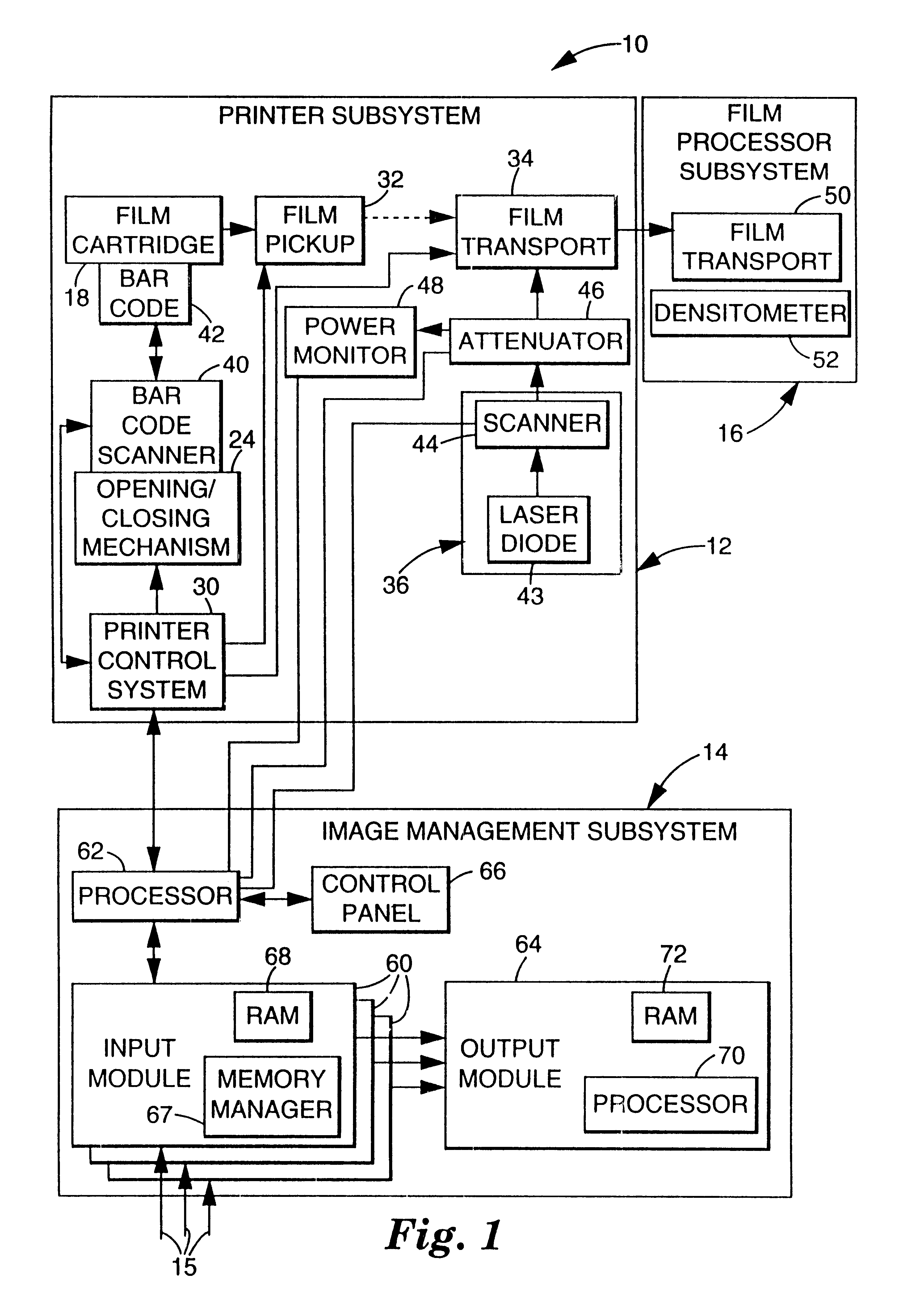
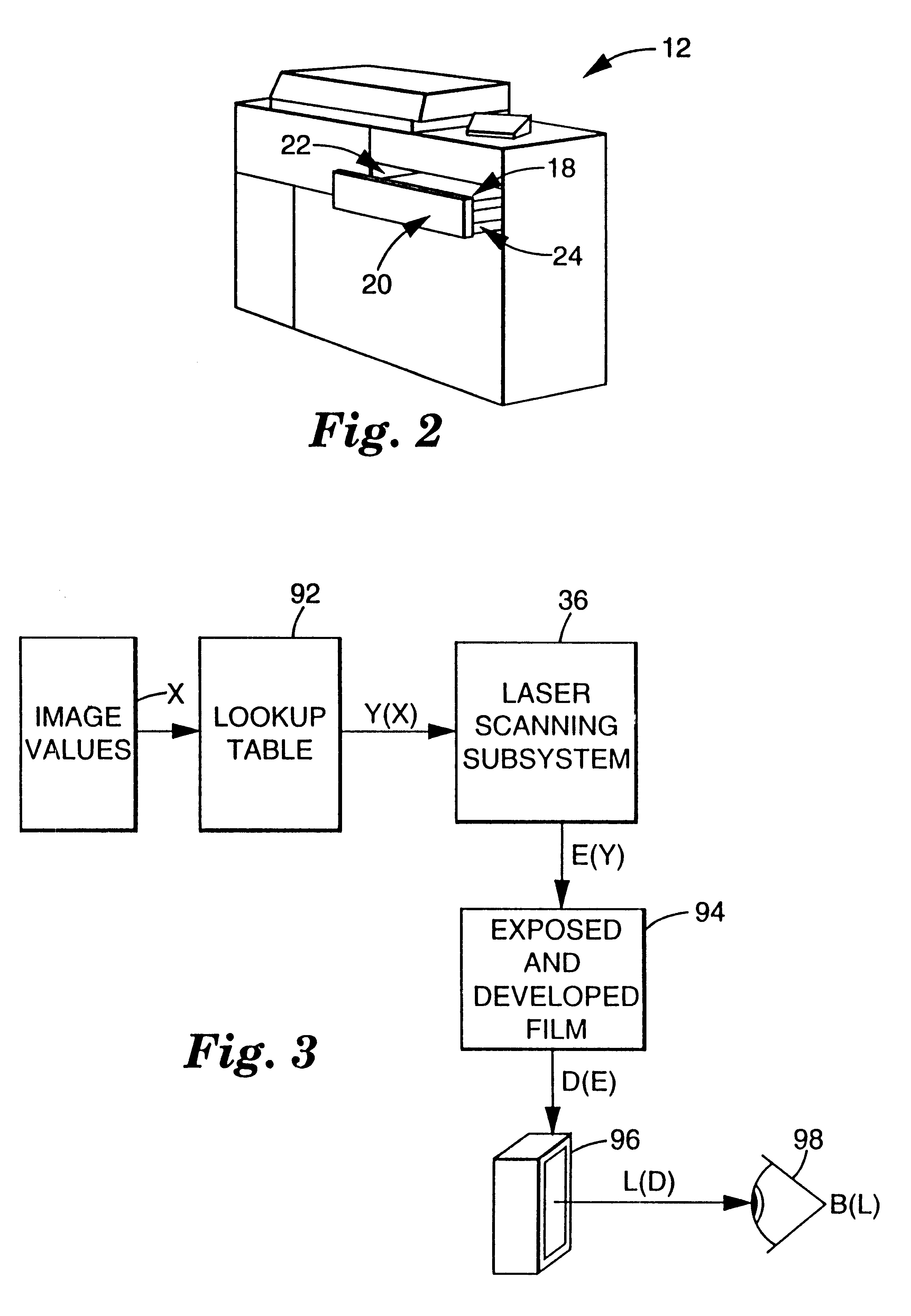
A multi-user digital laser imaging system 10 in accordance with the present invention is illustrated generally in FIG. 1. As shown, laser imaging system 10 includes laser diode printer subsystem 12, image management subsystem 14 and media processor subsystem 16. Printer subsystem 12 is a continuous tone laser imager in one embodiment, and is configured to receive resealable cartridges 18 which contain sheets of radiographic film (not separately shown). Image management subsystem 14 includes input ports 15 through which digital image values generated by a magnetic resonance (MR), computed tomography (CT) or other type of scanner are provided to imaging system 10. The image values are processed by image management subsystem 14 to generate laser drive values which are applied to printer subsystem 12 to image or expose film removed from cartridge 18. The printed film is subsequently developed by processor subsystem 16 to produce a hardcopy of the image. Imaging system 10 is


PUM


Abstract

A multi-user digital laser imaging system for imaging film from bar coded cartridges as a function of image values representative of the images to be printed. The imaging system includes memory for storing transfer functions and film models for each of several users. The transfer functions characterize the relationships between image values and expected imaged film transmittance quantities. The film models characterize the relationship between the transmittance quantities and laser drive values that will provide the appropriate film exposure. An image management subsystem generates lookup tables characterizing the relationship between image values and laser drive values on the basis of user-selected transfer functions and film models selected by the system through the use of film identification information read from the bar code. During imaging operations the image management subsystem accesses the lookup tables as a function of the image values to obtain the appropriate laser drive values. The transfer functions can be modified to accommodate user preferences. Test wedge calibration procedures are periodically implemented to correlate the film models to measured sensitometric characteristics. Density patch calibration procedures are performed during each imaging operation to correct for drifts caused by the film developing subsystem.

Description


Claims


Application Information

Patent Timeline
Owner CARESTREAM HEALTH INC
Why Eureka
Try Eureka