Thrust bearing

A technology of thrust bearings and thrust bearing bushes, applied in the field of thrust bearings, which can solve the problems of poor cooling effect, difficulty in forming oil film, burning of thrust bearings, etc., and achieve the effects of controlling radial swing range, prolonging service life, and uniform force bearing surface

Active Publication Date: 2009-04-08
NANJING HIGH SPEED & ACCURATE GEAR GRP
View PDF0 Cites 6 Cited by
  • Summary
  • Abstract
  • Description
  • Claims
  • Application Information

AI Technical Summary

Problems solved by technology

[0003] The purpose of the present invention is to solve the practical problems of poor cooling effect, high temperature, difficulty in forming an oil film, easy burning of th

Method used


Image

  • Thrust bearing
  • Thrust bearing
  • Thrust bearing

Examples


Embodiment Construction

[0021] The accompanying drawings non-restrictively disclose the specific structure of an embodiment of the present invention. The present invention will be further described below in conjunction with the accompanying drawings.

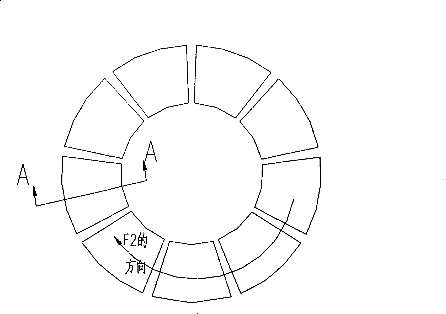
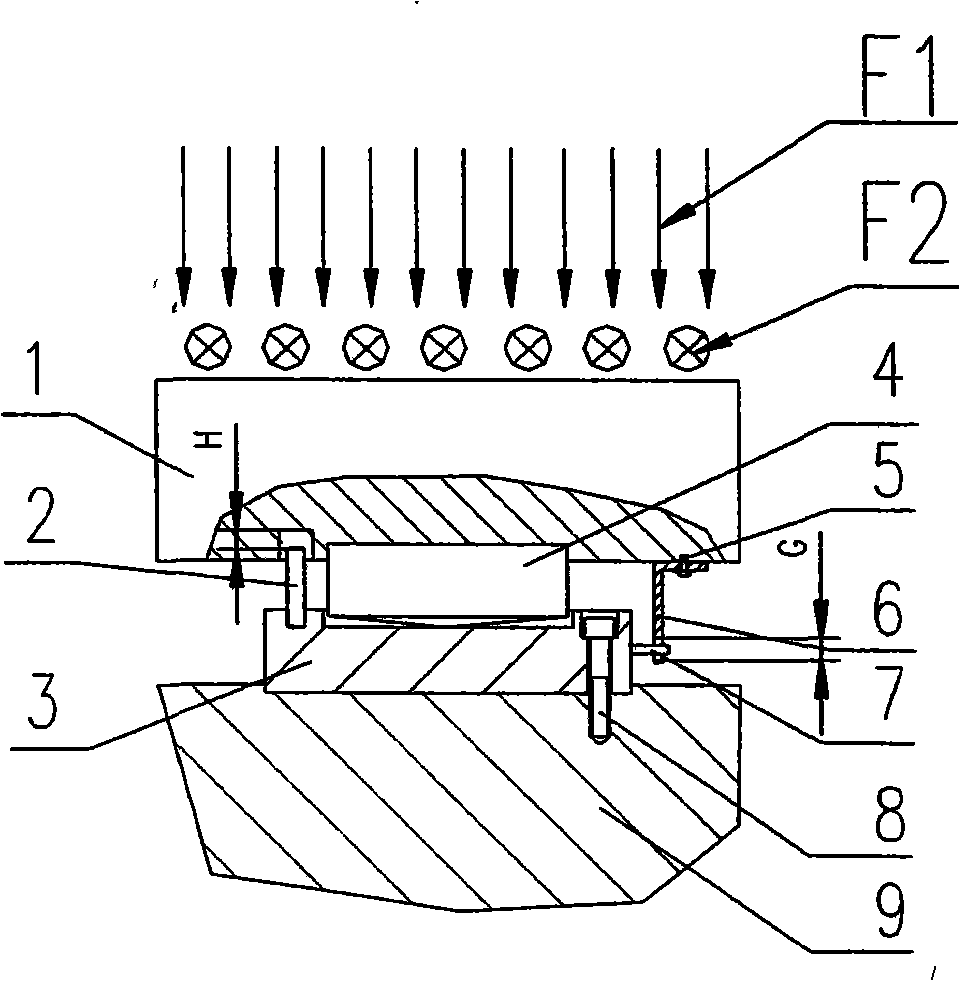
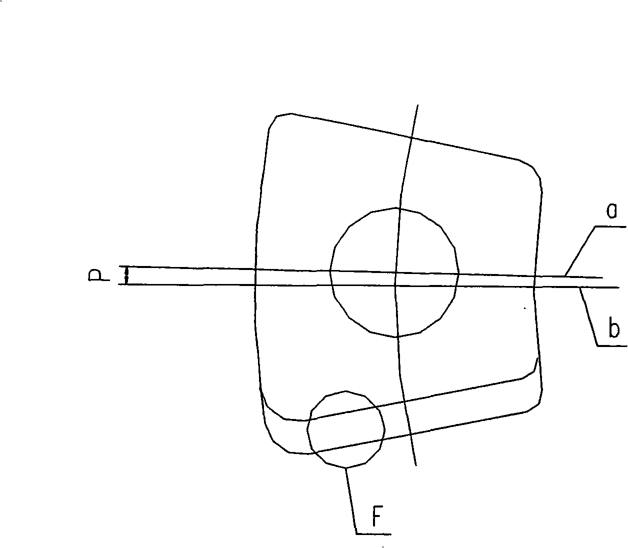
[0022] by figure 1 figure 2 Combine image 3 It can be seen that the present invention includes 6 to 24 independent thrust bearing groups, each of which contains a corresponding thrust bearing 1 and a supporting pad 3. The upper surface of the thrust bearing 1 is covered with a Babbitt alloy layer. The independent thrust The bearing group is evenly distributed on the same annular plane. A support block 4 is arranged between the thrust bearing 1 and the support pad 3. The lower end surface of the support block 4 is a spherical arc surface; the horizontal force direction F2 of the thrust bearing is taken as a reference , In a ring with evenly distributed thrust bushes 1, the radial centerline a of each support block lags the geometric centerline b of the cor


PUM


Abstract

The invention relates to a thrust bearing, which is characterized by comprising 6 to 24 thrust bearing pad groups; each thrust bearing pad group comprises thrust bearing pads and a supporting pad; the independent thrust bearing pad groups are evenly distributed on a same ring-shaped plane; a supporting block is arranged between the thrust bearing pads and the supporting pad; the lower-part end surface of the supporting pad is a spherical cambered surface; and the radial central line of each supporting block lags behind the geometric central line of the corresponding thrust bearing pads. The thrust bearing has the advantages that as a plurality of groups of thrust bearing pads and the supporting block of the spherical cambered surface are adopted, the stress surfaces of the thrust bearings are even; stop pins effectively control the radial swinging width of the thrust bearing pads; as the radial central line of the supporting block lags behind the geometric central line of the thrust bearing pads, and due to wedge-shaped lubricating oil inlets, oil films are easily formed on the surface of the thrust bearing pads so as to reduce the temperature of touching surfaces; both the supporting block and the stop pins can prevent the thrust bearing pads and the supporting pad from being deviated; among a plurality of independent thrust bearing pads, individual thrust bearing pad can be replaced separately, and therefore the maintenance cost is reduced.

Description


Claims


Application Information

Patent Timeline
Owner NANJING HIGH SPEED & ACCURATE GEAR GRP
Why Eureka
Try Eureka