Method for the combination of a post-increasing steel beam and a concrete slab

A technology for concrete slabs and steel beams, applied in the direction of joists, girders, truss beams, etc., can solve problems such as inapplicability of technical transformation projects, and achieve the effect of effective treatment methods

Inactive Publication Date: 2009-06-03
GUIYANG AL-MG DESIGN & RES INST
View PDF0 Cites 9 Cited by
  • Summary
  • Abstract
  • Description
  • Claims
  • Application Information

AI Technical Summary

Problems solved by technology

For the method of combining steel beams and concrete slabs, shear connectors (such as: channel steel, bending bars, etc.) are currently used for combination. This method is use

Method used


Image

  • Method for the combination of a post-increasing steel beam and a concrete slab

Examples


Embodiment Construction

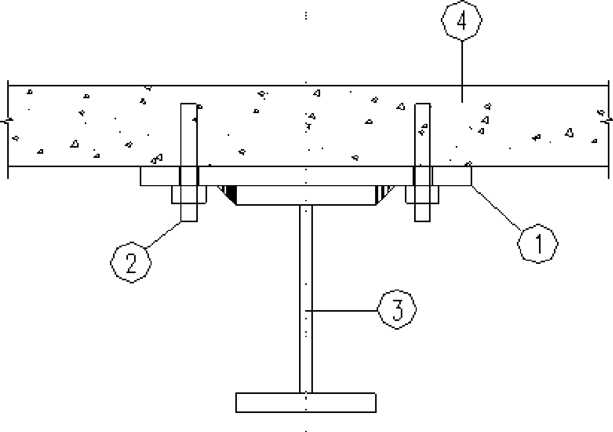
[0008] Embodiment of the present invention: make parts such as connecting steel plate 1, post-anchor building anchor bolt 2, post-reinforced steel beam 3, and carry out the combined construction of post-reinforced steel beam and concrete slab according to the diagram. Firstly, the positions of the post-increased steel beam 3 and the connecting steel plate 1 are determined on the bottom surface of the built concrete slab 4; secondly, the post-anchoring building anchor bolt 2 is anchored into the built concrete slab 4 at the position of the connecting steel plate 1; then , use post-anchoring building anchor bolts 2 to fix the connecting steel plate 1 on the bottom surface of the built concrete slab 4; finally, weld the post-increased steel beam 3 to the connecting steel plate 1.


PUM


Abstract

The invention discloses a method for the combination of a post-increasing steel beam and a concrete slab. Firstly, the location of a post-increasing steel beam (3) and a connecting steel plate (1) is determined on the bottom surface of a built concrete slab (4); secondly, a post-anchoring building anchor bolt (2) is anchored in the built concrete slab (4) at the location of the connecting steel plate (1); then the connecting steel plate (1) is fixed on the bottom surface of the built concrete slab (4) by the post-anchoring building anchor bolt (2); finally, the post-increasing steel beam (3) and the connecting steel plate (1) are connected. The invention uses the post-anchoring building anchor bolt for replacing the traditional shearing connecting piece, is used for bearing the vertical shearing force between the superimposing surfaces of the steel beam and the reinforced concrete slab, restricts the relative sliding of the steel beam and the reinforced concrete slab, causes the steel beam and the reinforced concrete slab to be combined into a whole and work reliably, and provides a simple and effective processing method for the technical transformation of the combination structure of the steel and the concrete.

Description


Claims


Application Information

Patent Timeline
Owner GUIYANG AL-MG DESIGN & RES INST
Why Eureka
Try Eureka