Non-wetting coating on a fluid ejector

A fluid ejector, wetting layer technology, applied in the direction of coating, metal material coating process, device for coating liquid on the surface, etc., can solve the problems of difficult to form patterns, expensive paint, not durable paint, etc. Droplet size, effect of improving reliability

Active Publication Date: 2009-09-23
FUJIFILM DIMATIX
View PDF2 Cites 8 Cited by
  • Summary
  • Abstract
  • Description
  • Claims
  • Application Information

AI Technical Summary

Benefits of technology

This technology helps improve the performance of an airless liquid dispenser (LDI) without causing excessive buildup of fluids around it's opening. It also prevents damage caused during cleanings between uses for different types of liquids.

Problems solved by technology

The technical problem addressed in this patented technology relating to liquid jet printing devices involves how to prevent excessive buildup of liquids onto their components when they shouldn't get done properly during use. This could lead to damage caused by overheating or other issues that might affect performance if left unattended for too long without being able to correct them effectively.

Method used


Image

  • Non-wetting coating on a fluid ejector
  • Non-wetting coating on a fluid ejector
  • Non-wetting coating on a fluid ejector

Examples


Embodiment Construction

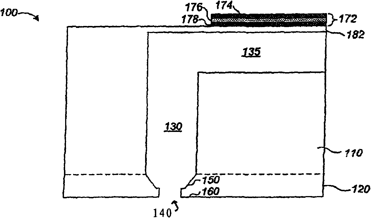
[0023] Figure 1A is a cross-sectional view of an uncoated fluid ejector 100 (e.g., an inkjet printhead nozzle) that can be configured as described in U.S. Patent Application Serial No. 11 / 256669 filed October 21, 2005. As stated above, the contents of US Patent Application Serial No. 11 / 256669 are incorporated herein by reference. Uncoated fluid ejector 100 includes flow channel module 110 and nozzle layer 120, both of which may be made of silicon (eg, single crystal silicon). In one embodiment, uncoated fluid ejector 100 is a single unit, and flow channel module 110 and nozzle layer 120 are not separate components. Diaphragm layer 182 is located above pumping chamber 135 . Actuator 172 pressurizes fluid (eg, ink, eg, water-based ink) in pumping chamber 135 . Fluid flows through down channels 130 and is ejected through holes 140 in nozzle layer 120 . The actuator 172 may include a piezoelectric layer 176, a lower electrode 178 (eg, a ground electrode), and an upper electr


PUM


Abstract

A fluid ejector having a first surface, a second surface, and an orifice that allows fluid in contact with the second surface to be ejected. The fluid ejector has a non-wetting layer exposed on at least a first surface of the fluid ejector, and a overcoat layer exposed on a second surface, the overcoat layer being more wetting than the non-wetting layer. Fabrication of this apparatus can include depositing a non-wetting layer on the first and second surfaces, masking the first surface, optionally removing the non-wetting layer from the second surface, and depositing an overcoat layer on the second surface.

Description


Claims


Application Information

Patent Timeline
Owner FUJIFILM DIMATIX
Why Eureka
Try Eureka