Miniaturized coaxial cavity tunable filter with balanced bandwidths at high end and low end

A filter and coaxial cavity technology, applied in the field of microwave passive circuits, can solve the problems of high and low-end bandwidth imbalance, large volume, etc., and achieve the effect of maintaining a constant bandwidth

Inactive Publication Date: 2010-02-03
HANGZHOU DIANZI UNIV
View PDF0 Cites 0 Cited by
  • Summary
  • Abstract
  • Description
  • Claims
  • Application Information

AI Technical Summary

Benefits of technology

This technology uses two different structures: filters that are coupled together by windows or rings made up from rectangles instead of circular arcs; and couplings between these components which decrease gradually over time due to increasing frequencies. These improvements allow for complete adjustment throughout all possible frequency ranges without sacrificing resolution capabilities at high speeds.

Problems solved by technology

This patented technical problem addressed in the patents relates to improving the design for an improved type of coaxium cavity (C) tuned filter used with electronic devices such as mobile phones or tablets due to their limited space requirements. Specifically, there has been increasing demand towards smaller sizes while maintaining high quality signals transmitted over longer distances without compromising electrical insulation properties. To address these issues, previous designs had limitations in achieving desired results.

Method used


Image

  • Miniaturized coaxial cavity tunable filter with balanced bandwidths at high end and low end
  • Miniaturized coaxial cavity tunable filter with balanced bandwidths at high end and low end
  • Miniaturized coaxial cavity tunable filter with balanced bandwidths at high end and low end

Examples


Embodiment Construction

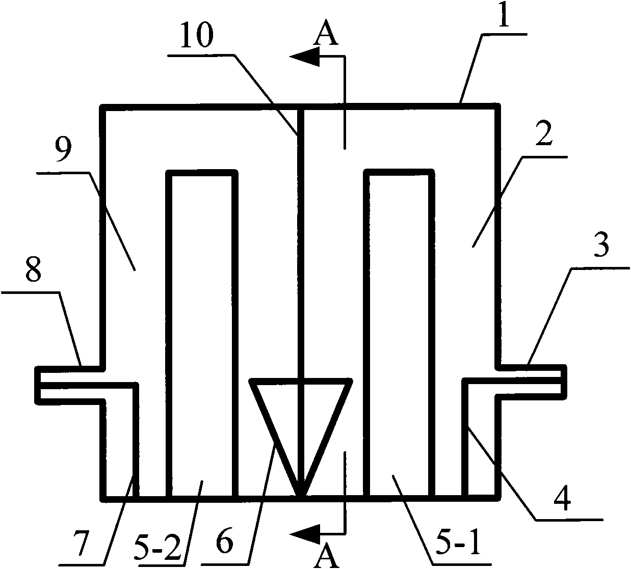
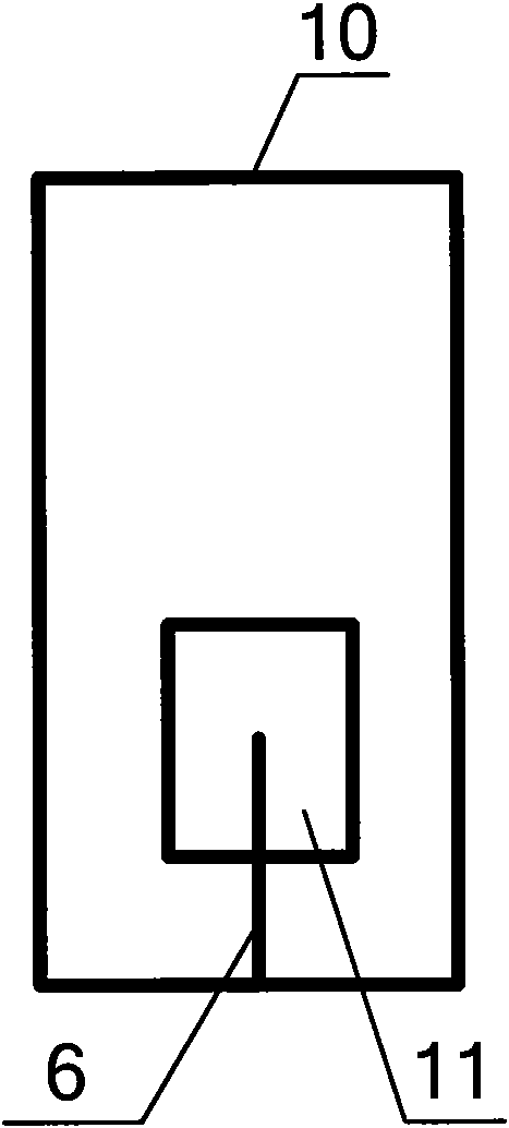
[0018] Such as figure 1 and figure 2 As shown, a miniaturized coaxial cavity tunable filter with balanced high-end and low-end bandwidth includes: filter housing 1, partition 10, input coaxial connector 8, output coaxial connector 3, input coupling ring 7, output Coupling ring 4. The front cover of the filter housing 1 is provided with an input coaxial connector 8, the input coaxial connector 8 is connected to one end of the input coupling ring 7, and the other end of the input coupling ring 7 is connected to the bottom of the filter housing 1; A partition 10 is arranged in the middle, and the partition 10 divides the filter housing 1 into a front coaxial cavity 9 and a rear coaxial cavity 2; a rectangular coupling window 11 is opened on the partition 10, which is an inverted isosceles triangle-shaped cavity The bottom edge of the coupling ring 6 is set through the coupling window 11, the plane where the intercavity coupling ring 6 is located is perpendicular to the plane wher


PUM


Abstract

The invention relates to a miniaturized coaxial cavity tunable filter with balanced bandwidths at a high end and a low end. The prior coaxial cavity tunable filter can not maintain a constant bandwidth at different frequency bands. The miniaturized coaxial cavity tunable filter comprises a filter shell and a baffle plate, wherein a front end cover and a back end cover of the filter shell are provided with coaxial joints; the baffle plate is arranged in the middle of the filter shell; a rectangular coupling window is arranged on the baffle plate; the bottom edge of an inter-cavity coupling looppasses through the coupling window to be arranged; the plane where the inter-cavity coupling loop is arranged is perpendicular to the plane where the rectangular coupling window is arranged; two waists of the inter-cavity coupling loop are respectively positioned in a front coaxial cavity and a back coaxial cavity; and the top point of the inter-cavity coupling loop is positioned in the middle point of a line section where the jointing part of the baffle plate and the bottom of the filter shell is positioned. In the invention, the coupling window of the filter is combined with the inter-cavity triangular coupling loop, and the structure can be used for enabling the bandwidth of the coaxial cavity tunable filter to be constant in the whole frequency tuning range.

Description


Claims


Application Information

Patent Timeline
Owner HANGZHOU DIANZI UNIV
Why Eureka
Try Eureka