Heat dissipation method of LED lamp and LED lamp adopting same
A technology of LED lamps and heat dissipation methods, which is applied to cooling/heating devices of lighting devices, lighting and heating equipment, parts of lighting devices, etc., can solve problems such as poor heat dissipation, and achieve easy production, high luminous efficiency, and luminous The effect of low shading
- Summary
- Abstract
- Description
- Claims
- Application Information
AI Technical Summary
Problems solved by technology
Method used
Image

Examples
Example Embodiment
[0029] Embodiment one
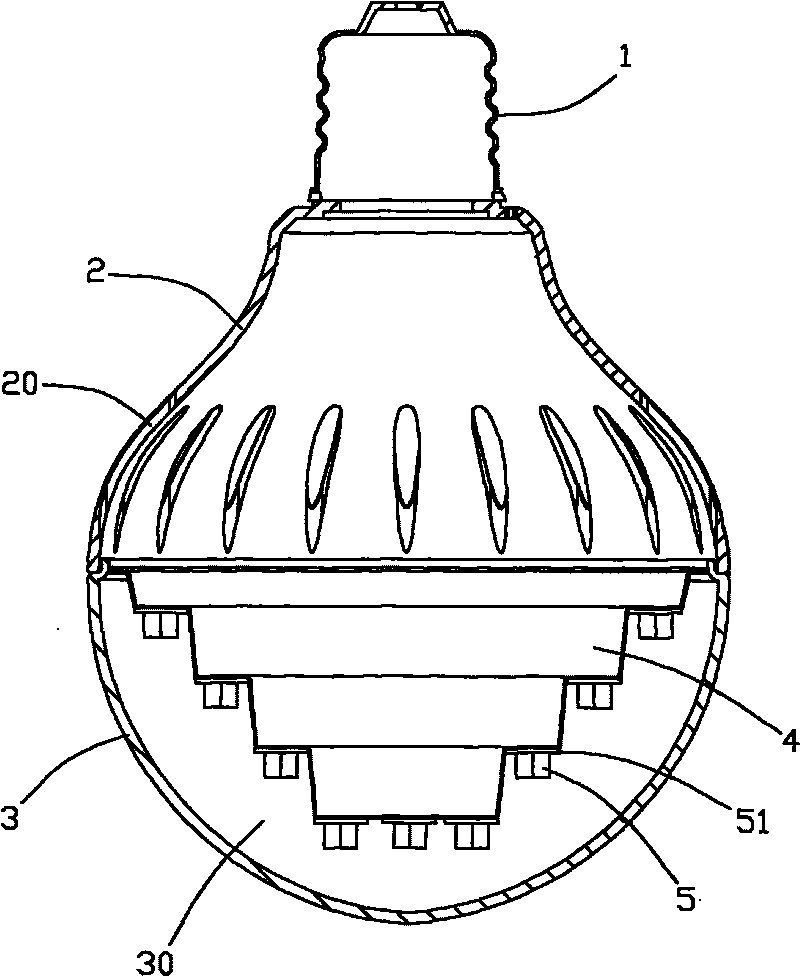
[0030] A kind of LED lamp, refer to figure 1 , including a lamp holder 1, a plastic shell 2, a glass shell 3, a heat dissipation component 4, an LED assembly 5 and a power supply module for powering the LED assembly 5, which is not shown in the figure. The plastic case 2 is connected between the lamp cap 1 and the glass case 3 , and the above-mentioned power module can be arranged in the plastic case 2 to supply power for each LED assembly 5 . The heat dissipation component 4 is built in the glass shell 3, and a heat transfer cavity 30 is formed between the heat dissipation component 4 and the glass shell 3, and the heat transfer cavity 30 is filled with a heat transfer medium gas. Each LED assembly 5 is pasted on the heat dissipation component 5 through the heat conduction substrate 51 .
[0031] refer to figure 1 , the heat dissipation component 4 is a cup-shaped body with a stepped side wall. Each LED assembly 5 is arranged on the bottom surface of
Example Embodiment
[0033] Embodiment two
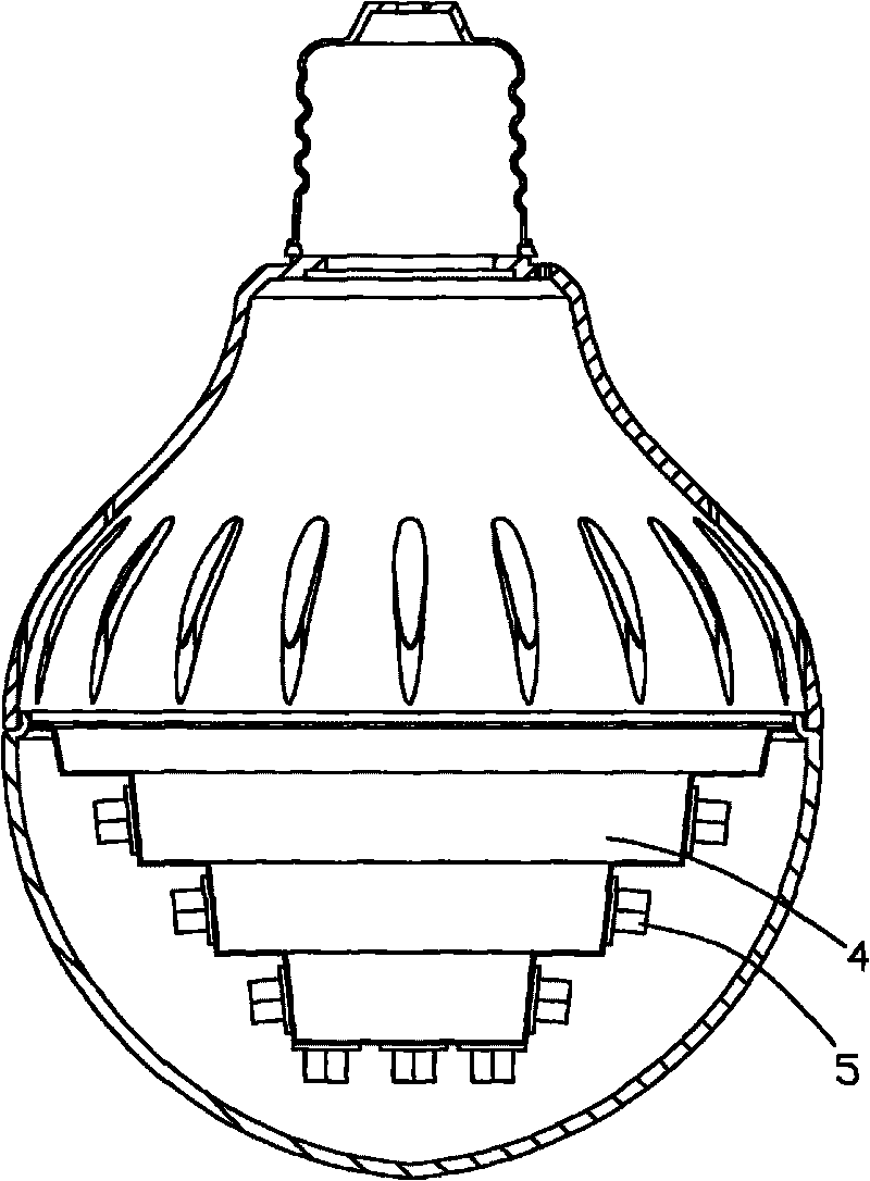
[0034] refer to figure 2 , the structure of this embodiment is basically the same as that of Embodiment 1, the only difference is that each LED assembly 5 of this embodiment is arranged on the side of each step of the cup-shaped heat dissipation part 4, and the side of each step is a tapered surface, Therefore, the light emitting angle of this embodiment is larger than that of the first embodiment.
Example Embodiment
[0035] Embodiment Three
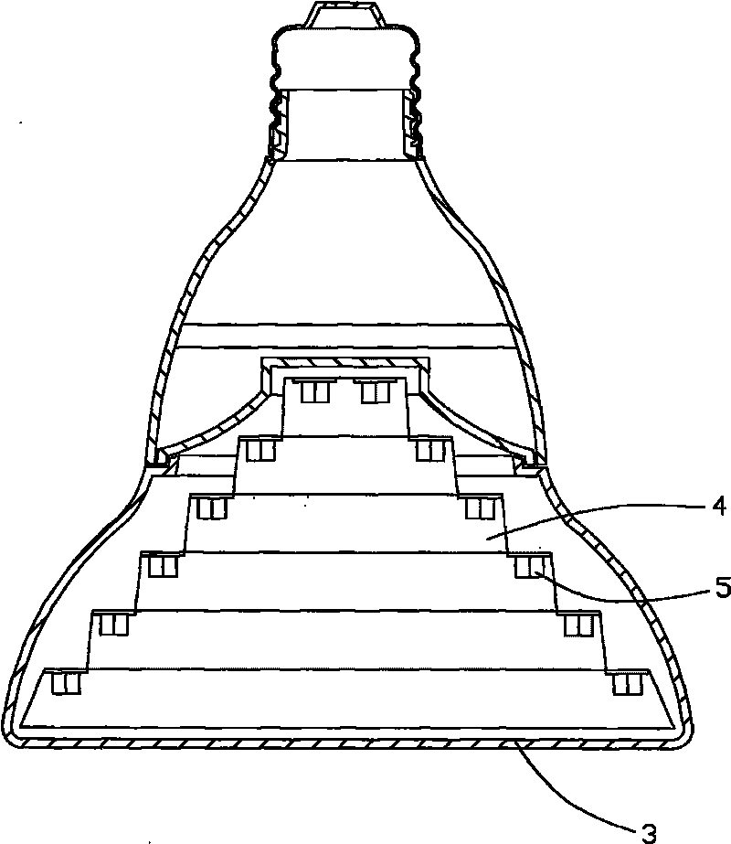
[0036] refer to image 3 , the structure of this embodiment is basically the same as that of Embodiment 1, the difference between the two is that the cup mouth of the cup-shaped heat dissipation part 4 faces the side of the glass shell 3, and the heat dissipation part 4 is concave inward when viewed from the side of the glass shell 3 of. Each LED assembly 5 is also arranged on the bottom surface of each step of the cup-shaped heat dissipation component 4 . In order to adapt to the shape of the heat dissipation part 4 , the shape of the glass envelope 3 of this embodiment is also different from that of the first embodiment.
PUM
 Abstract
Description
Claims
Application Information
 - R&D Engineer
- R&D Manager
- IP Professional
- Industry Leading Data Capabilities
- Powerful AI technology
- Patent DNA Extraction
Browse by: Latest US Patents, China's latest patents, Technical Efficacy Thesaurus, Application Domain, Technology Topic.
© 2024 PatSnap. All rights reserved.Legal|Privacy policy|Modern Slavery Act Transparency Statement|Sitemap