Light-emitting diode lamp

Inactive Publication Date: 2010-06-09
FU ZHUN PRECISION IND SHENZHEN +1
View PDF0 Cites 8 Cited by
  • Summary
  • Abstract
  • Description
  • Claims
  • Application Information

AI Technical Summary

Benefits of technology

Problems solved by technology

The technical problem addressed in this patented text relates to improving the durability and efficiency of LED lights that use semiconducers made from materials like gallium nitride (GaN). However, current methods have issues where there may occur leakage during assembly due to imperfections caused by adhesive residues at edges along the interface between the two components. This could result in reduced reliance upon longer lifetimes and potential damaging effects over time.

Method used


Image

  • Light-emitting diode lamp
  • Light-emitting diode lamp
  • Light-emitting diode lamp

Examples


Embodiment Construction

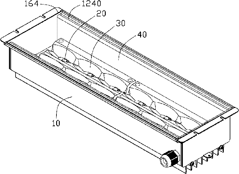
[0011] see figure 1 The light-emitting diode lamp according to one embodiment of the present invention includes a lamp holder 10, a light-emitting diode module 20 accommodated in the lamp holder 10, two light guide plates 30 covering the light-emitting diode module 20, and a cover placed on the light-emitting diode module 20. A vertically long transparent lampshade 40 covering the LED module 20 and the light guide plate 30 is provided on the top surface of the lamp holder 10 .

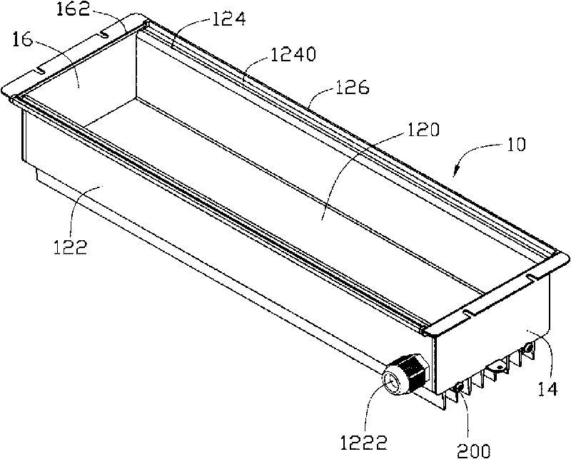
[0012] Please also see figure 2 and image 3 The above-mentioned lamp holder 10 is a hollow cavity with an opening (not marked) as a whole, which includes a longitudinal groove-shaped mounting frame 12, two baffle plates 14 respectively fixed on the opposite ends of the mounting frame 12, and clamped respectively. There are two sealing pads 16 between the installation frame 12 and the second baffle plate 14 . The mounting frame 12 includes a rectangular mounting plate 120, two side walls 122 extending


PUM


Abstract

A light-emitting diode (LED) lamp comprises a lamp holder which is like a hollow cavity and is provided with an opening, an LED module arranged in the cavity of the lamp holder and a lampshade covering the opening of the lamp holder and the LED module. The lamp holder comprises a lengthwise groove-shaped installation rack and two baffles respectively arranged at two opposite ends of the installation rack. Two accommodating grooves respectively positioned at two opposite sides of the installation rack are arranged at the top of the installation rack. A base plate is stuck between each baffle and the installation rack. The tops of the base plates, the end edge of the lampshade and the tops of the baffles encircle two grooves together. The two grooves are respectively positioned at two opposite ends of the opening of the lamp holder. The grooves and the accommodating grooves surround the opening of the lamp holder and accommodate sealing glue so as to connect the lampshade and the lamp holder in a sealed manner. Compared with the prior art, the invention is characterized in that the structures of the accommodating grooves and the grooves ensure the sealing glue to be uniformly distributed, thus improving the overall sealing property of the lamp and being not easy to befoul the transparent lampshade so as to affect the lighting effect and the appearance of the lamp.

Description


Claims


Application Information

Patent Timeline
Owner FU ZHUN PRECISION IND SHENZHEN
Why Eureka
Try Eureka