Feeding mechanism for numerical control double surface lapping machine

A double-sided grinding and feeding mechanism technology, applied in the grinding field, can solve problems such as inconvenient operation, out-of-tolerance workpiece size, and inaccurate measurement accuracy

Active Publication Date: 2010-09-15
XINXIANG SUNRISE CNC BEARING EQUIP
View PDF5 Cites 0 Cited by
  • Summary
  • Abstract
  • Description
  • Claims
  • Application Information

AI Technical Summary

Problems solved by technology

[0002] The existing CNC double-sided grinding machine is combined by the cylinder on the cylinder support, and the piston rod of the cylinder is connected with the upper grinding disc through the shaft. When working, the cylinder first drives the upper grinding disc to contact the lower grinding disc and makes the mea

Method used


Image

  • Feeding mechanism for numerical control double surface lapping machine
  • Feeding mechanism for numerical control double surface lapping machine
  • Feeding mechanism for numerical control double surface lapping machine

Examples


Embodiment Construction

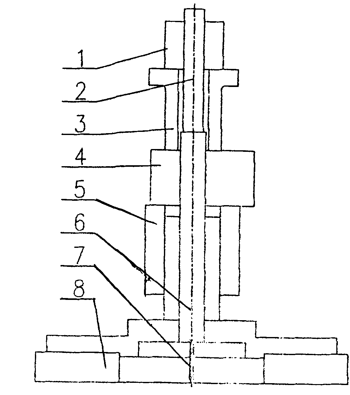
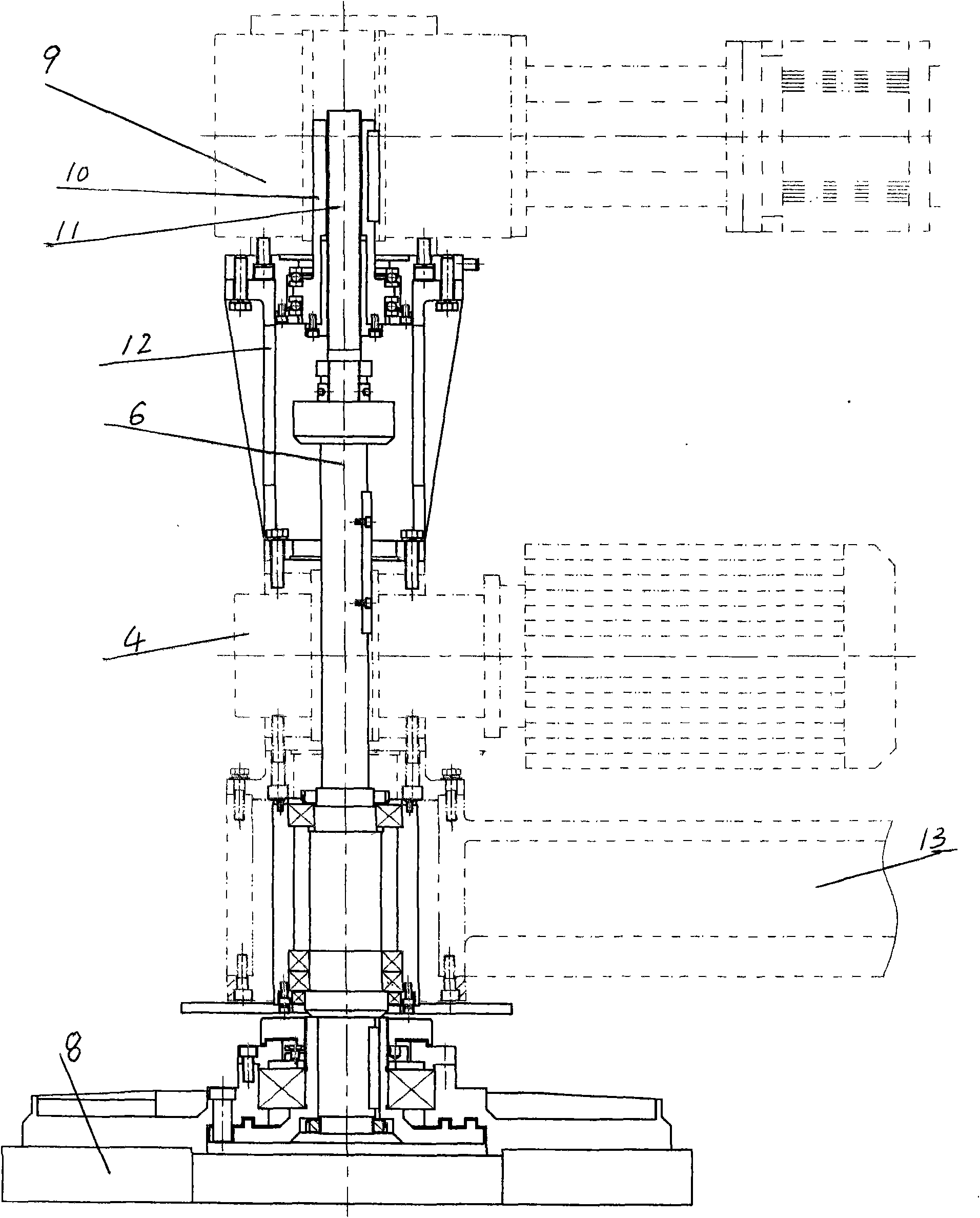
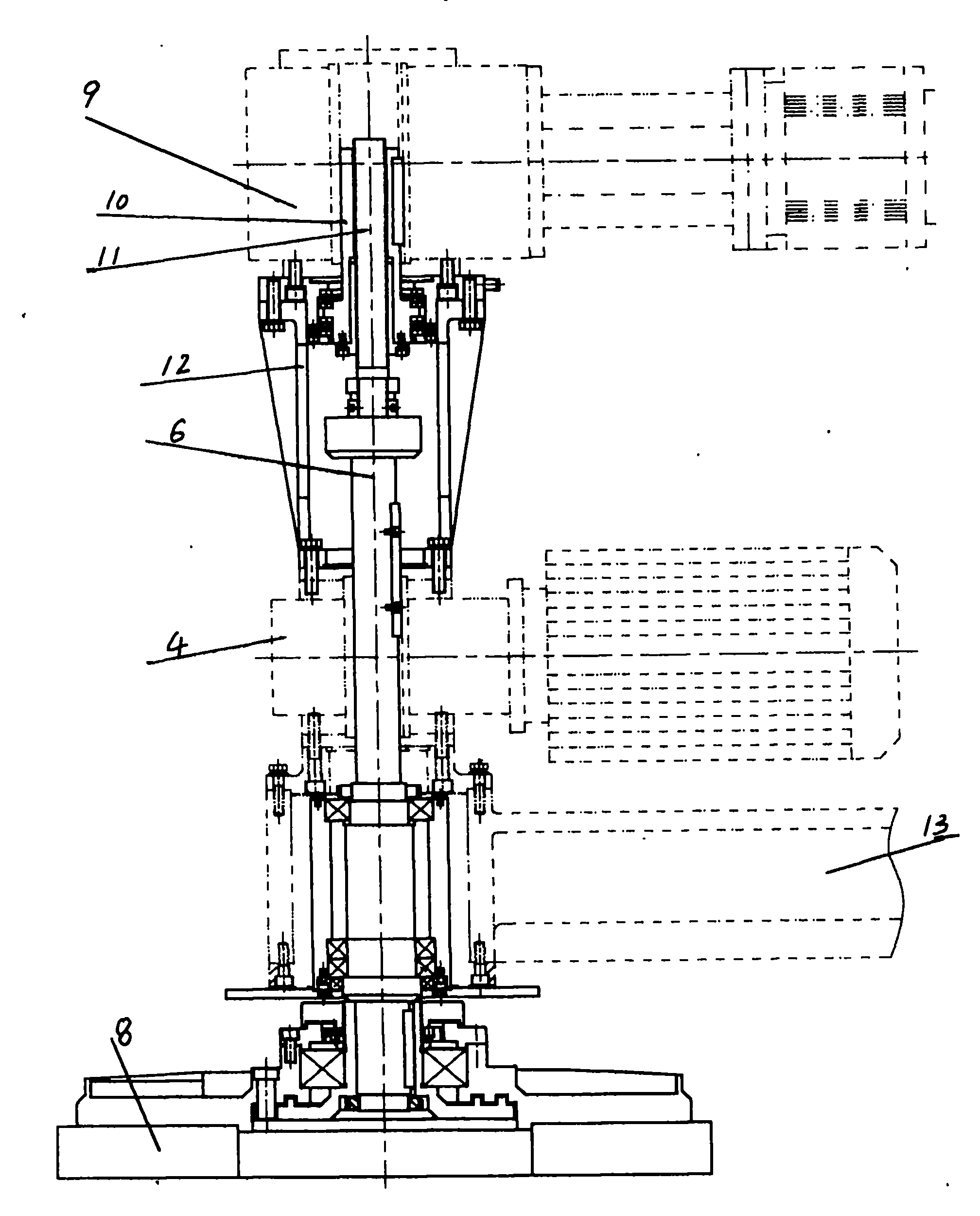
[0006] The embodiment is described in detail in conjunction with the above accompanying drawings. In the prior art, the cylinder 1 is combined on the cylinder support 3, the cylinder piston rod 2 is connected with the upper grinding disc 8 through the shaft 6, and the reduction motor 4 is installed under the cylinder support 3. Guide sleeve 5 and measuring head 7, (see figure 1 ), when working, the piston rod 2 in the cylinder drives the upper grinding disc to move through the shaft 6. In the present invention, the servo motor 9 is combined on the motor support 12, the motor support is fixed on the reduction motor 4 with screws, the reduction motor is fixed on the rocker arm 13 with screws, and the other end of the rocker arm 13 is sleeved on the bed On the column, you can shake the rocker arm back and forth by hand to center the upper and lower grinding discs. The ball screw cover 10 is equipped with a ball screw 1, which is driven by the servo motor to rotate, so that the ball


PUM


Abstract

The invention discloses a feeding mechanism for a numerical control double surface lapping machine and aims to provide an accurate, stable and reliable feeding mechanism, in particular a feeding mechanism for the numerical control double surface lapping machine, which can realize automatic compensation of workpiece thickness. The feeding mechanism comprises a speed-reducing motor, a shaft, a measuring head, and an upper lapping disk. A servo motor is engaged on a motor stand; the motor stand is fixed on the speed-reducing motor through a screw; the speed-reducing motor is fixed on a rocker arm through a screw; and a ball screw is sleeved inside a ball screw sleeve. The feeding mechanism for the numerical control double surface lapping machine has the advantages that: the feeding mechanism is controlled by the servo motor and fed by the ball screw; the workpiece is positioned in a good working state during accurately and reliably lapping the workpiece; the constant grinding is realized; the grinded workpiece has high precision, and the automatic compensation of the workpiece thickness can be realized.

Description


Claims


Application Information

Patent Timeline
Owner XINXIANG SUNRISE CNC BEARING EQUIP
Why Eureka
Try Eureka