Digital television receiver

A technology of digital TV signal and TV signal, which is applied in the direction of TV, color TV, color TV parts, etc., and can solve the problem that it is impossible to reuse

Inactive Publication Date: 2011-04-27
NOVABASE DIGITAL TV TECH
View PDF0 Cites 1 Cited by
  • Summary
  • Abstract
  • Description
  • Claims
  • Application Information

AI Technical Summary

Problems solved by technology

[0006] In addition, specific set-top boxes must still be fully developed, tested and validated f

Method used


Image

  • Digital television receiver
  • Digital television receiver
  • Digital television receiver

Examples


Embodiment Construction

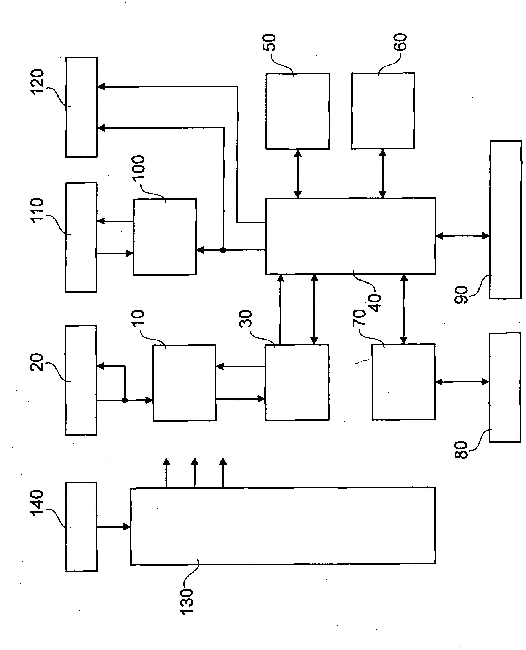
[0051] figure 1 Shows the basic structure of an apparatus for receiving digital television signals, for example in the form of a set-top box, top view. In this case, the motherboard houses multiple component groups and components. exist figure 1 In the illustrated embodiment, the main board 150 houses the tuner IC 10 , the demodulator IC 30 , and the HF signal port 20 . These components may also be referred to as front-end components. The main board 150 also accommodates a so-called back-end processor IC 40 , RAM memory 50 , flash memory 60 and smart card IC 70 . These components are generally referred to as backend components. Control and display elements 90 are also provided on the operating system. The board also houses a remodulator assembly pack 100 , a remodulator HF port 110 and a number of RCA / Toslink audio and video outputs 120 . A power circuit 130 and a power port 140 may also be provided for energy supply.

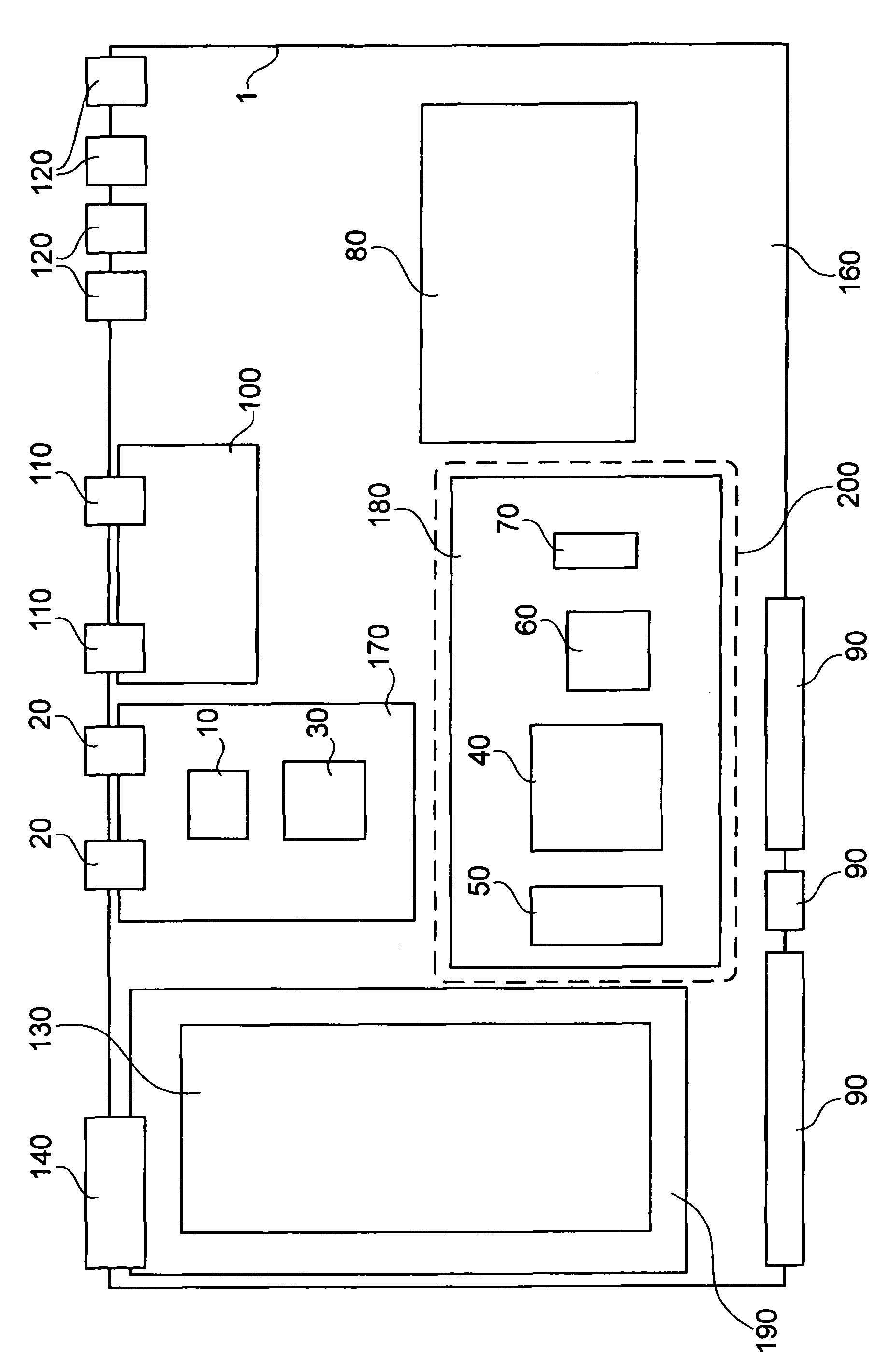
[0052] figure 2 shows the structural design of th


PUM


Abstract

The present invention relates to a device for receiving digital television signals, as well as to a data processing module for digital television signals, wherein a device is provided for receiving digital television signals, with a main board and a module board port, wherein the module board port is provided on the main board, wherein the module board port exhibits an input interface, which is suitable for the one digital input data stream, and an output interface, which is suitable for an output signal, e.g., a television output signal in various forms.

Description


Claims


Application Information

Patent Timeline
Owner NOVABASE DIGITAL TV TECH
Why Eureka
Try Eureka