Method for measuring groove position of inner bearing ring

A technology of bearing inner sleeve and measurement method, applied in the direction of mechanical clearance measurement, etc., can solve the problems of increasing the production cost of the enterprise, the error of the actual groove position value and the actual assembly groove position value, and the different measurement methods, so as to reduce the production cost and improve the The effect of measurement accuracy and simple measurement method

Inactive Publication Date: 2011-05-11
浙江斯菱汽车轴承股份有限公司
View PDF0 Cites 2 Cited by
  • Summary
  • Abstract
  • Description
  • Claims
  • Application Information

AI Technical Summary

Benefits of technology

This patented technology allows for precise measurements without being limited or requiring complicated equipment like an optical fiber probe used during testing. It achieves this through calculating various factors such as grooves' positions on the inside surface of bearings while they assemble them into their final product. By accurately determining these variables, it becomes possible to achieve very high-precision results even if there may be issues affecting its performance. Overall, this innovation simplifies manufacture processes and increases production rates while minimizing costs.

Problems solved by technology

This patented technical problem addressed in this patents relates to improving the accuracy of measuring the location or depth inside bushes on bearings during manufacture without requiring expensive equipment such as calibrators that are used manually.

Method used


Image

  • Method for measuring groove position of inner bearing ring
  • Method for measuring groove position of inner bearing ring

Examples


Embodiment Construction

[0017] The present invention will be described in further detail below in conjunction with the accompanying drawings and embodiments.

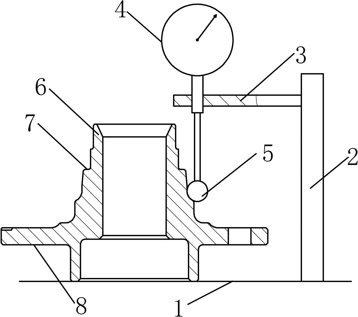
[0018] See attached picture. The present embodiment includes a base 1 as a measuring plane, on which a column 2 is vertically fixed, on the column 2 there is a connecting rod 3 parallel to the base, on which a thousand points Instrument 4; the measuring end of the micrometer 4 is a measuring ball 5, and the diameter d of the measuring ball 5 is the same as the channel radius R of the bearing inner sleeve 6 under test.

[0019] Using the above-mentioned measuring device, when measuring in this embodiment, the height H of the end surface of the inner sleeve 6 of the bearing under test is firstly measured by the pad gauge method. 实 and the height C of the assembly surface of the bearing inner sleeve 6 under test 实 ; Then according to the theoretical value A of the bearing inner sleeve groove position 0 and the end face height H of the bearing in


PUM


Abstract

The invention discloses a method for measuring the groove position of an inner bearing ring, which comprises the following steps of: a, preparing a micrometer, and arranging a measuring ball of which the diameter d is the same with the radius R of a measured groove at the measuring end of the micrometer; b, measuring the end surface height H real of a measured inner bearing ring; c, measuring the assembly surface height C real of the measured inner bearing ring; d, adjusting the distance E between the lower end of the measuring ball of the micrometer and a measuring plane according to a theoretical value A0 of the groove and the end surface height H real of the measured inner bearing ring, wherein the E=(H real-A0)-d/2; e, putting the measured inner bearing ring on the measuring plane, making the arc of the groove completely match with that of the measuring ball of the micrometer, and obtaining the reading X real of the micrometer; f, calculating the real groove position A real of the measured inner bearing ring, wherein the A real=H real-X real; and g, calculating the real groove assembly position B real of a measured bearing, wherein the B real=X real-C real. The method has the characteristics of simplicity for measurement, convenience for operation and high detection accuracy.

Description


Claims


Application Information

Patent Timeline
Owner 浙江斯菱汽车轴承股份有限公司
Why Eureka
Try Eureka