Slurry density sensor

A density sensor and sensor technology, applied in the field of sensors, can solve problems such as poor fluidity, achieve the effects of improving sensitivity and accuracy, increasing flow speed, and reducing diameter

Inactive Publication Date: 2011-10-19
CHENGDUSNJIANG GEOTECHN TECH
View PDF7 Cites 2 Cited by
  • Summary
  • Abstract
  • Description
  • Claims
  • Application Information

AI Technical Summary

Problems solved by technology

[0004] At present, the detection of slurry density in engineering is mainly through the distance between the sensor and the slurry outlet plane ( is calculated with the cement slurry outlet plane as the datum plane), such as image 3 shown, according to to get the density of the slurry , but in actual production, due to the characteristics of the slurry,

Method used


Image

  • Slurry density sensor
  • Slurry density sensor
  • Slurry density sensor

Examples


Embodiment Construction

[0023] The present invention will be further described below in conjunction with the accompanying drawings, but the scope of protection is not limited to the description.

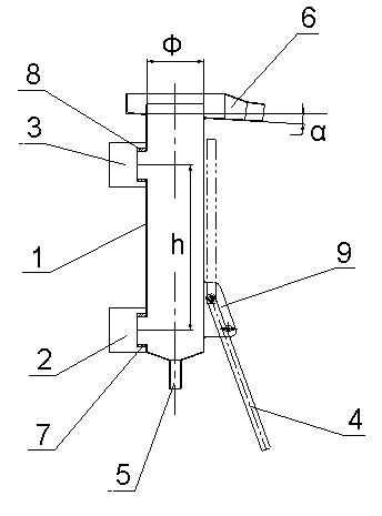
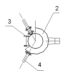
[0024] Such as figure 1 , figure 2 , a kind of slurry density sensor, it comprises standard measuring barrel, sensor A2, sensor B3 and tripod 4, and the lower end of standard measuring barrel 1 is provided with cement slurry inlet 5, and upper end is provided with slurry outlet 6, and side wall is provided with distance The threaded mounting port A7 and the threaded mounting port B8 are h, the threaded mounting port B8 is located above the threaded mounting port A7 and the threaded mounting port A7 and the threaded mounting port B8 are on the same axis, and the sensor A2 and the sensor B3 are respectively installed on the threaded mounting port A7 and the threaded mounting port B8 and fixed with screws, the side wall of the standard measuring barrel 1 is provided with a tripod fixing frame 9, the tripod 4 i


PUM


Abstract

The invention discloses a slurry density sensor, which comprises a standard measurement bucket (1), a sensor A (2), a sensor B (3) and a foot stand (4). The lower end of the standard measurement bucket (1) is provided with a cement slurry inlet (5), and the upper end of the standard measurement bucket (1) is provided with a slurry outlet (6). A screw mounting opening A (7) and a screw mounting opening B (8) are formed at the interval of h on the sidewall of the standard measurement bucket (1). Density is calculated according to a formula. The slurry density sensor changes the selection of a reference height in the prior art and uses a fixed height so as to greatly improve the sensitivity and accuracy of the density sensor and more accurately and timely reflect a density parameter of slurry, simultaneously reduces the diameter of the standard measurement bucket so as to increase the flow velocity of the slurry, prolong the service life of the sensor and further reduce sensor replacement and disassembly times and the production cost, and has a wide application range.

Description


Claims


Application Information

Patent Timeline
Owner CHENGDUSNJIANG GEOTECHN TECH
Why Eureka
Try Eureka