Secondary oscillating joint structure of underwater electric manipulator
An electric manipulator and joint structure technology, applied in the directions of manipulators, electric components, control mechanical energy, etc., can solve the problems of system energy loss or complex structure, and achieve the effect of easy processing, easy installation and compact structure
- Summary
- Abstract
- Description
- Claims
- Application Information
AI Technical Summary
Benefits of technology
Problems solved by technology
Method used
Image

Examples
Embodiment approach 1
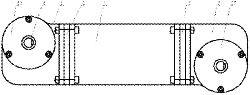
[0046] Such as figure 2 As shown, the outer layer of the present invention includes a cavity structure and a cover structure. The cavity structure includes box body 1, joint fixing flange 9 and box body 15; the cover plate structure includes motor support plate 6, motor support plate 13, end cover 30, end cover 35, end cover 42 and end cover 43.
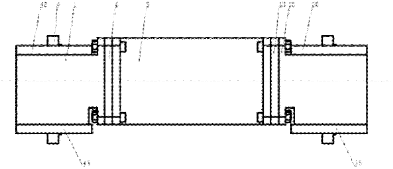
[0047] Such as Figure 4 As shown, the installation form of the left and right structures in the figure is the same. The joint fixing flange 9, the motor assembly support plate 13 and the worm gear casing 15 are fixedly connected by bolts and nuts through four flanges. The joint fixing flange 9 and the motor assembly support plate 13, and the static seal ring 25 and the static seal ring 26 are arranged between the motor assembly support plate 13 and the worm gear casing 15. The DC brushless servo deceleration motor assembly 10 is connected to the motor assembly fixing plate 11 by screws, and the motor assembly fixing plate 11 is con
Embodiment approach
[0049] This embodiment can make the structure serve as a joint with less axial force on the power output shaft of the underwater manipulator.
Embodiment approach 2
[0051] Such as Figure 7 As shown, the end cover 30 is fixedly connected with the worm gear casing 15 by screws, and is sealed by a sealing ring 31 . A resolver rotor 39 is installed on the right side of the worm gear output shaft 28 , and they are connected by a key 40 , and the resolver stator 38 is embedded in the end cover 35 . The sliding bearing 45 is embedded in the worm gear casing 15 to radially locate the right side of the worm output shaft 28 , and the one-way thrust ball bearing 44 is embedded in the worm gear casing 15 to axially locate the right side of the worm output shaft 28 . The worm wheel 27 is connected with the worm wheel output shaft 28 through the key 29, and the axle sleeve 32 plays the role of axially positioning the worm wheel 27. The left side of the worm gear output shaft 28 is supported by a flange sliding bearing 34 . The flanged sliding bearing 34 is embedded in the end cover 30 . The end cover 30 is fixedly connected with the worm gear casing 1
PUM
 Abstract
Description
Claims
Application Information
 - R&D Engineer
- R&D Manager
- IP Professional
- Industry Leading Data Capabilities
- Powerful AI technology
- Patent DNA Extraction
Browse by: Latest US Patents, China's latest patents, Technical Efficacy Thesaurus, Application Domain, Technology Topic.
© 2024 PatSnap. All rights reserved.Legal|Privacy policy|Modern Slavery Act Transparency Statement|Sitemap