Method and device for measuring optical fiber asymmetry time delay

A technology of symmetrical time delay and optical fiber measurement, applied in the field of optical communication, can solve the problems of inconvenient portability, low test efficiency, expensive instruments, etc., and achieve the effect of overcoming the limited number of instruments, short stable test time, and improved test efficiency

Active Publication Date: 2011-12-21
FENGHUO COMM SCI & TECH CO LTD
View PDF3 Cites 27 Cited by
  • Summary
  • Abstract
  • Description
  • Claims
  • Application Information

AI Technical Summary

Problems solved by technology

[0004] (1) The instrument is expensive, inconvenient to carry, and limited by the site
[0005] (2) The number of instruments is generally limited. The test needs to set up a satellite antenna, and it takes a long time to stabilize when receiving satellite timing. It will also be affected by factors such as weather and angle of view. The influence of cable connection length on the results, the test method is more complicated, and the test efficiency is low
[0006] (3) The instrument test is a relative test. The test result is affected by the accuracy of the time synchronization equipment and the satellite timing drift, and the error is relatively large. The test work needs to be carried out step by step from the source. If the previous test is not accurate, It will inevitably affect the results of subordinate tests
Therefore, the test accuracy is not high and cannot meet the needs of large-scale engineering applications

Method used


Image

  • Method and device for measuring optical fiber asymmetry time delay
  • Method and device for measuring optical fiber asymmetry time delay
  • Method and device for measuring optical fiber asymmetry time delay

Examples


Embodiment Construction

[0036] The present invention will be further described in detail below in conjunction with the accompanying drawings and embodiments.

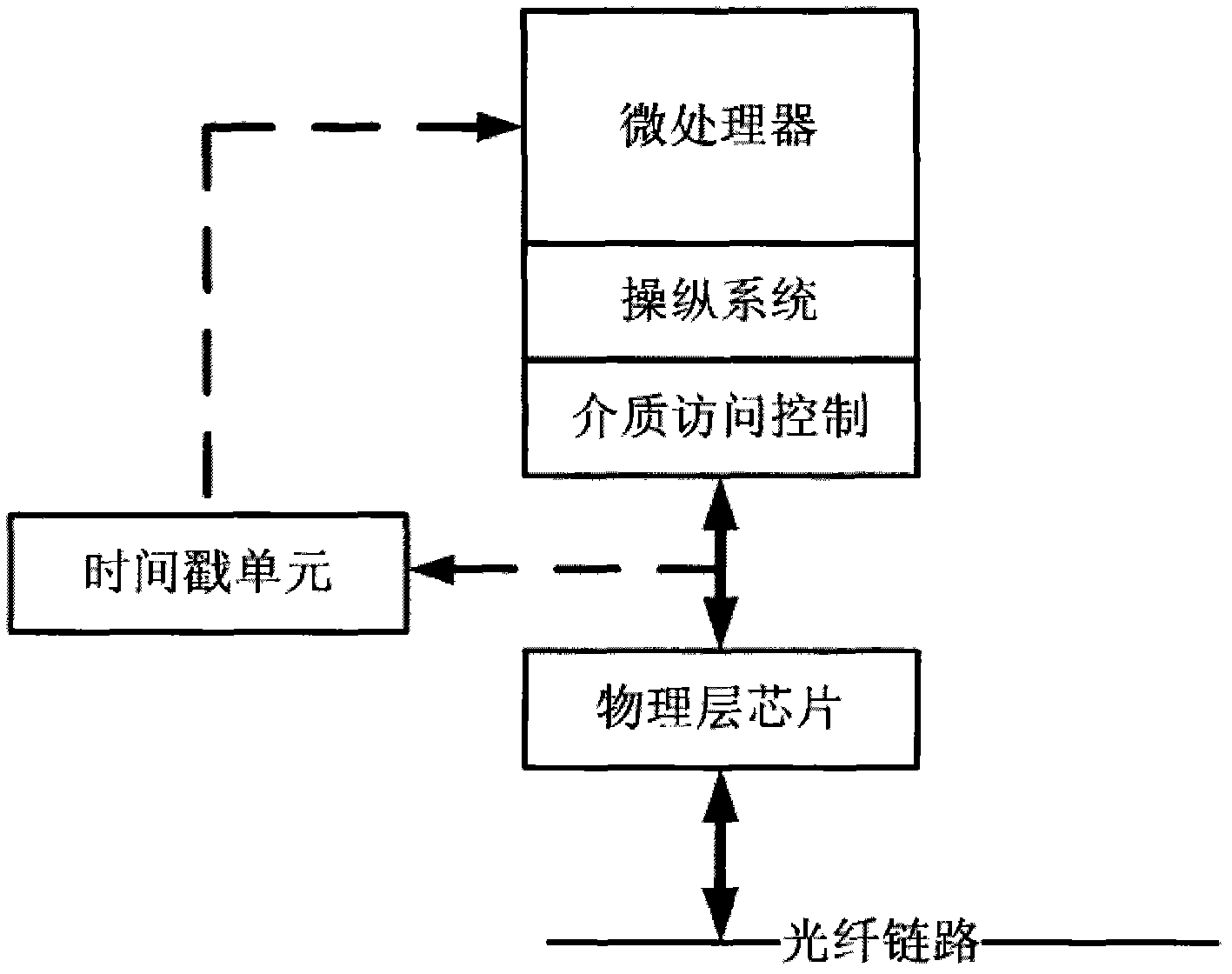
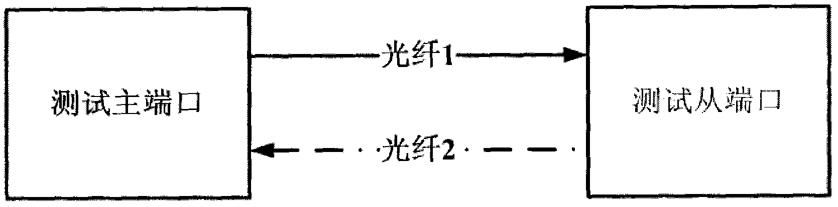
[0037] see figure 1 As shown, the device for measuring fiber asymmetry delay provided by the embodiment of the present invention includes TSU (Timestamp Unit, time stamp unit), PPU (Protocol Processing Unit, protocol processing unit), ACU (Analysis and Calculation Unit, analysis and calculation unit) and RTU (Remote control unit, remote control unit), where:

[0038] The TSU is used to generate and record time stamp information t1 when the Master side sends a test message, and write the time stamp information t1 into the test message for transmission or transmit the time stamp information t1 to the PPU according to the test message mode; when the Slave side When receiving the test message, generate and record the time stamp information t2. The TSU needs to ensure sufficient precision and stability, and the precision and stability of the time...


PUM


Abstract

Disclosed are a method and apparatus for measuring optical fiber asymmetry time delay. The method comprises: an RTU configuring working states of a Master and a Slave at two ends of an optical fiber line; the RTU delivering an instruction to measure a first optical fiber, and a Master side PPU sending a message, recording a sending time stamp t1 and transmitting the sending time stamp t1 to the Slave; a Slave side PPU receiving the message, recording an arrival time stamp t2, and storing the arrival time stamp t2 corresponding to t1; the RTU displaying that measurement for the first optical fiber is completed, preparing to measure a second optical fiber, and swapping the two optical fibers; the RTU delivering an instruction to measure the second optical fiber, and the Master side PPU sending a message, recording a sending time stamp t'1 and transmitting the sending time stamp t'1 to the Slave; the Slave side PPU receiving the message, recording an arrival time stamp t'2, and storing the arrival time stamp t'2 corresponding to t'1; and an ACU calculating an asymmetry time delay compensation value and sending the asymmetry time delay compensation value to the RTU. The present invention is not limited by sites, saves cost and labor, is simple and fast, and has short stabilization time as well as high testing efficiency and precision.

Description

technical field [0001] The invention relates to the field of optical communication, in particular to a method and a device for measuring the asymmetric time delay of an optical fiber. Background technique [0002] As a modern mobile communication service bearer network, the optical communication network needs to implement the time synchronization function of IEEE1588v2 (1588 time synchronization protocol v2 version formulated by IEEE), and transmit time synchronization information to each network node to achieve high-precision time synchronization. For IEEE1588v2 time synchronization, the line asymmetry caused by the inconsistency of optical fiber lengths in the sending direction and receiving direction on the optical interface will directly affect the accuracy of time synchronization. Therefore, to deploy an IEEE1588v2 time synchronization network in an optical communication network, it is necessary to accurately measure the asymmetry existing in the line, and use the measu...

Claims


Application Information

Patent Timeline
IPC IPC(8): H04B10/08H04B10/077H04B10/079
CPCH04B10/0773H04J3/0682
Inventor 陈朝辉方琼孙涛
Owner FENGHUO COMM SCI & TECH CO LTD
Why Eureka
Try Eureka