Small electric motor and method for manufacturing the same

A kind of electric motor, small technology, applied in the direction of manufacturing motor generators, electric components, electrical components, etc., can solve the problem of inflexible conception, achieve the effect of simple method, low cost, and simplified assembly operation

Active Publication Date: 2012-02-01
MAXON MOTOR AG
View PDF4 Cites 4 Cited by
  • Summary
  • Abstract
  • Description
  • Claims
  • Application Information

AI Technical Summary

Benefits of technology

The technical effect of this patented technology lies within that when two parts (the connector or stator) are connected together by welding them onto their respective teeth on one side of each other's poles with strong adhesive tape. These connections make installation time-consuming but provide high reliability for long periods without requiring expensive equipment like soldering tools.

Problems solved by technology

Technological Problem: The technical problem addressed by this patented technology relates to improving the efficiency and performance of electronic devices while reducing their sizes without compromising their functionality. Specifically, there needs to improve how these electronics connect wirelessly at smaller distances within the device's enclosure.

Method used


Image

  • Small electric motor and method for manufacturing the same
  • Small electric motor and method for manufacturing the same
  • Small electric motor and method for manufacturing the same

Examples


Embodiment Construction

[0022] In the following, like reference numerals are used to refer to like parts.

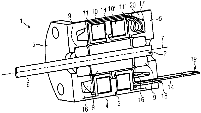
[0023] Such as figure 1 As shown, a small electric motor 1 according to the present invention is configured in the manner of a claw pole motor and includes a rotor 2, a stator 3, and a housing 4 which is firmly connected to the stator 3 and whose two ends pass through The corresponding housing cover 5 is axially closed. The stator 3 of the claw-pole motor 1 according to the invention comprises two stator coils 10 and 10 ′, which are endowed with a ring-like structure and arranged coaxially with the axis of rotation 7 of the rotor 2 . Each of the stator coils 10 and 10' is bonded to an associated pole tooth edge 11 and 11', respectively, and the stator coils 10 and 10' adjoin each other in the axial direction. Stator coils 10 and 10 ′ are surrounded on the outside by housing 4 . The rotor 2 of the claw pole motor 1 according to the invention consists essentially of a hollow cylindrical permanen


PUM


Abstract

The invention relates to a small electric motor and a method for manufacturing the same. The small electric motor is preferably provided with a claw pole motor. The small electric motor includes a housing, a stator having at least two stator windings, a rotor having a rotational axis, and a flexible conductor foil for the electrical connection of the stator windings. The conductor foil includes winding connection contacts, external connection contacts and conductor paths between the winding connection contacts and the external connection contacts. Taps of the stator windings are electrically contacted with the winding connection contacts of the conductor foil. The conductor foil can be configured as an elongated strip having at least two connection portions which are arranged in spaced-apart relationship with each other and include winding connection contacts.

Description


Claims


Application Information

Patent Timeline
Owner MAXON MOTOR AG
Why Eureka
Try Eureka