Cleaning device and cleaning method

A technology for cleaning devices and cleaning tanks, which is applied to cleaning methods and utensils, cleaning methods using liquids, chemical instruments and methods, etc., which can solve the problems of not being able to spray cleaning liquid and achieve a stable cleaning effect

Active Publication Date: 2012-04-11
MIURA COMPANY LIMITED
View PDF13 Cites 11 Cited by
  • Summary
  • Abstract
  • Description
  • Claims
  • Application Information

AI Technical Summary

Benefits of technology

This patented technology allows for efficient cleanup without damaging fragile items being treated while maintaining their safety level. It involves adding an oxygen-containing gas (O2) to the purification bath through pipes that are placed under specific conditions. These technical means aim to generate stable foam patterns around the surface area containing the cleanliness solution, which helps remove stubborn dirt particles efficiently. Additionally, the use of a special device called a vaporizer prevents explosions caused by igniting combustible gases within the system. Overall, this process provides improved efficiency and accuracy in cleaning processes involving high temperatures and pressures.

Problems solved by technology

This patented technical problem addressed in these inventions relates to improving the efficiency and effectiveness of cleaning objects such as laundry during various stages of their manufacture. Specifically, current methods involve filling empty spaces within the body of each item separately after they have been treated together, but this can lead to issues like overheating certain parts that may damage them if too much moisture enters through condensations caused by insufficiently humidifying upstream areas where dirt particles tend to stick tightly onto clothes when dry-cleaning techniques involving steam injection cannot remove stubborn residue effectively without adding energy beyond what would otherwise cause boiled stones. Additionally, previous solutions require multiple steps before reaching steady state, leading to longer processing times compared to other existing technologies.

Method used


Image

  • Cleaning device and cleaning method
  • Cleaning device and cleaning method
  • Cleaning device and cleaning method

Examples


Embodiment 1

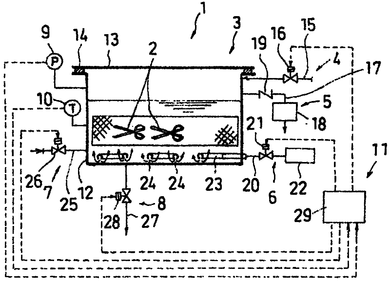
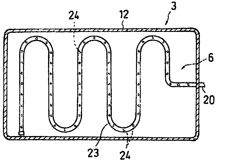
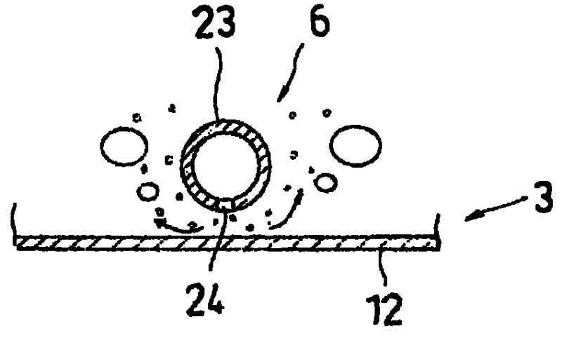
[0050] figure 1 It is a schematic configuration diagram showing Embodiment 1 of the cleaning device of the present invention, and a part thereof is shown in cross-section. in addition, figure 2 is a schematic cross-sectional view of a cleaning tank of the cleaning device. and then, image 3 yes figure 2 A schematic longitudinal sectional view of a part of , showing a state in which gas is introduced into the cleaning liquid.

[0051] The cleaning device 1 of the present embodiment is provided with: a cleaning tank 3, wherein the cleaning liquid is accumulated and the object to be cleaned 2 is immersed; a water supply mechanism 4, which supplies the cleaning liquid into the cleaning tank 3; The gas is sucked and discharged to the outside to reduce the pressure in the cleaning tank 3; the gas supply mechanism 6 is used to introduce gas into the cleaning solution in the cleaning tank 3; the heating mechanism 7 is used to heat the cleaning solution in the cleaning tank 3; Drai

Embodiment 2

[0083] Figure 5 It is a schematic configuration diagram showing Embodiment 2 of the cleaning device 1 of the present invention, and a part thereof is shown in cross-section. The cleaning device 1 of the second embodiment is basically the same as that of the first embodiment. Here, the following description will focus on the differences between the two, and the corresponding parts will be described with the same reference numerals.

[0084] The cleaning device 1 of the present embodiment 2 is equipped with: a cleaning tank 3, wherein the cleaning liquid is accumulated and the object 2 to be cleaned is immersed; a water supply mechanism 4, which supplies the cleaning liquid to the cleaning tank 3; The gas in the cleaning tank 3 is sucked and discharged to the outside to decompress the inside of the cleaning tank 3; the recompression mechanism 30 introduces external gas into the gas phase part of the decompressed cleaning tank 3 to restore the pressure in the cleaning tank 3 and r


PUM


Abstract

A cleaning liquid is contained in a cleaning tank (3), and an object (2) to be cleaned is immersed in the cleaning liquid. A pressure reducing means (5) reduces the pressure in the cleaning tank (3) by sucking gas in the cleaning tank (3) and discharging the gas to the outside. A heating means (7) heats the cleaning liquid within the cleaning tank (3). A gas supply means (6) introduces gas into the cleaning liquid within the cleaning tank (3) from a position below the object (2) to be cleaned. After the cleaning liquid is heated to a preset temperature by the heating means (7), the pressure within the cleaning tank (3) is reduced by the pressure reducing means (5) to boil the cleaning liquid, and the gas is introduced into the cleaning liquid by the gas supply means (6) during the boiling. By this, the cleaning liquid is fiercely boiled to increase the effect of cleaning of the object (2) to be cleaned.

Description


Claims


Application Information

Patent Timeline
Owner MIURA COMPANY LIMITED
Why Eureka
Try Eureka