Four-row cylindrical roller bearing special for steel rolling mill

A technology of cylindrical roller bearings and cylindrical rollers, applied in the field of bearings, can solve the problems of affecting the length of rollers, reducing the service life of bearings, stress concentration, etc., and achieve the effects of improving rigidity and strength, improving overall life, and improving bearing capacity

Inactive Publication Date: 2012-05-16
WAFANGDIAN ZHENGDA METALLURGICAL MILL BEARING
View PDF4 Cites 1 Cited by
  • Summary
  • Abstract
  • Description
  • Claims
  • Application Information

AI Technical Summary

Benefits of technology

This new design helps prevent damage from external forces such as pressure or vibration during use without compromising its performance. It also enhances the durability and lifespan of bearings by reducing stresses concentrations caused by these sources while maintaining sufficient space between them. Additionally, it allows for better control over how well they work when installed inside an axle housing due to their increased size compared to previous designs. Overall, this technology makes sure more reliable and long-lasting equipment are available at all times.

Problems solved by technology

The technical problem addressed in this patented text relates to how well bearings can handle heavy loads without being affected or breaking down overtime due to stresses from high temperatures during operation.

Method used


Image

  • Four-row cylindrical roller bearing special for steel rolling mill
  • Four-row cylindrical roller bearing special for steel rolling mill

Examples


Embodiment Construction

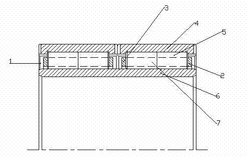
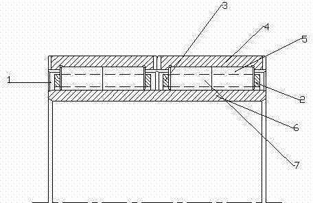
[0013] figure 1 The reference signs made are as follows: oil inlet 1, cage cover 2, cage seat 3, outer ring 4, cylindrical roller 5, inner ring 6, cage 7.

[0014] exist figure 1 In the schematic diagram of a four-row cylindrical roller bearing dedicated to a rolling mill shown, its main structure includes: an outer ring 4, a cage, a cylindrical roller 5, an inner ring 6 and an oil inlet 1; the outer ring 4 and the inner The rings 6 are respectively provided with raceways. The cylindrical rollers 5 are located between the two raceways and roll between the tracks of the outer ring 4 and the inner ring 6. A cage 7 is arranged between the inner ring 6 and the outer ring 4, and the outer ring 4 The oil inlet hole 1 is provided on the end face. The integral cage 7 is formed by the cage base 3 and the cage cover 2 through the rivets on the cage 7 and is connected into one by thermocompression. The middle of the cage base 3 and the cage cover 2 is naturally formed such as a dry pocket


PUM


Abstract

The invention discloses a four-row cylindrical roller bearing special for a steel rolling mill. The four-row cylindrical roller bearing is characterized by consisting of an outer ring, two holders, four rows of cylindrical rollers, an inner ring and an oil inlet hole, wherein the outer ring and the inner ring are provided with a raceway respectively; the cylindrical rollers are positioned between the two raceways, and roll between tracks of the outer ring and the inner ring; the holders are arranged between the inner ring and the outer ring; the oil inlet hole is formed in the end face of the outer ring; and two rows of cylindrical rollers are arranged in each holder.

Description


Claims


Application Information

Patent Timeline
Owner WAFANGDIAN ZHENGDA METALLURGICAL MILL BEARING
Why Eureka
Try Eureka