Pilot valve air tightness testing device

A test device and tightness technology, which is applied in the direction of liquid tightness measurement using liquid/vacuum, pipes/pipe joints/fittings, mechanical equipment, etc., which can solve the problems of low detection automation, high labor cost, and slow test speed, etc. problems, to achieve a high degree of detection automation, save labor costs, and ensure the effect of test accuracy

Inactive Publication Date: 2012-07-04
CHINA JILIANG UNIV
View PDF6 Cites 4 Cited by
  • Summary
  • Abstract
  • Description
  • Claims
  • Application Information

AI Technical Summary

Problems solved by technology

The existing domestic pilot valve air tightness test devices generally have the following problems: 1. Low degree of detection automation
Manually immerse the valve in water directly after ventilating the valve body during the testing process, and manual participation is required throughout the testing process; 2. The testing accuracy is low
During the testing process, due to the lack of good pressure maintenance, the gas passing into the valve body leaks when it is not immersed in water, resulting in inaccurate test results; 3. Most air tightness test devices for pilot valves require Assigning an operator to each station, the labor cost is high, the production efficiency is low, and it is not suitable for mass production; 4. Since the test process is not automated, the unskilled operation of the operator will cause the test speed to be slow

Method used


Image

  • Pilot valve air tightness testing device
  • Pilot valve air tightness testing device
  • Pilot valve air tightness testing device

Examples


Example Embodiment

[0020] The present invention will be further described below in conjunction with drawings and embodiments.

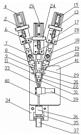
[0021] like figure 1 Shown, the present invention comprises E pipe high-pressure air intake mechanism, S pipe sealing mechanism, C pipe high-pressure air intake mechanism, D pipe sealing mechanism and stainless steel reflector; The air intake mechanism and the D pipe closing mechanism are respectively connected to the E pipe, S pipe, C pipe and D pipe of the pilot valve. The stainless steel tube reflector 41 is installed directly below the pilot valve 39. The reflector 41 is immersed in water through the mechanical structure, and the purpose of setting the stainless tube reflector 41 is to facilitate the operator to observe the air leakage of the lower part of the pilot valve, which improves the reliability of the test results.

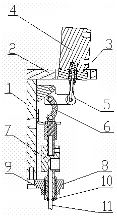
[0022] like figure 1 , figure 2 As shown, the E-pipe high-pressure intake mechanism includes: E-pipe support 1, first cylinder support 2, fir


PUM


Abstract

The invention discloses a pilot valve air tightness testing device, which comprises a high-pressure air inlet mechanism of a tube E, a closing mechanism of a tube S, a high-pressure air inlet mechanism of a tube C, a closing mechanism of a tube D and a stainless steel reflector. The high-pressure air inlet mechanism of the tube E, the closing mechanism of the tube S, the high-pressure air inlet mechanism of the tube C and the closing mechanism of the tube D are respectively connected with the tube E, the tube S, the tube C and the tube D of a pilot valve, and the stainless steel reflector is mounted right below the pilot valve. The pilot valve air tightness testing device is high in detection automation degree, realizes automation of sealing processes of the various tubes of the pilot valve, saves labor cost and improves testing efficiency; before air tightness is detected, a mechanical structure is used for applying force onto an O-shaped ring and leads the O-shaped ring to deform, so that the sealing effect of the various tubes is good, and testing precision is guaranteed; the stainless steel reflector is mounted and brings convenience for an operator to observe the condition of air leakage of the lower half portion of the pilot valve, and reliability of test results is improved; and the pilot valve to be detected is soaked into water or raised from the water by the mechanical structure, so that detection time is greatly shortened.

Description


Claims


Application Information

Patent Timeline
Owner CHINA JILIANG UNIV
Why Eureka
Try Eureka