Liquid crystal display device

A liquid crystal display device and graphics technology, applied in nonlinear optics, instruments, optics, etc., can solve problems such as contamination of liquid crystals, and achieve the effect of reducing afterimages

Inactive Publication Date: 2012-07-11
NANJING CEC PANDA LCD TECH
View PDF4 Cites 16 Cited by
  • Summary
  • Abstract
  • Description
  • Claims
  • Application Information

AI Technical Summary

Benefits of technology

This patented technology helps prevent bad quality pictures from being displayed due to improperly cured or damaged areas that may be located near these edges during manufacturing processes. By placing circular arcs along one side of an edge region with specific intervals between them, this prevents any harmful particles like oxygen gas entering into the device's interior causing damage when it works properly.

Problems solved by technology

This patented describes how conventional LC devices used in flat panels have limitations in achieving high resolutions without increasing their size. These technical solutions involve improving the performance of LCR technology over traditional methods like vacuum fluorescent lamps and cold cathodes. However, these techniques require expensive equipment and complicated processes which increase costs compared to what was previously possible before.

Method used


Image

  • Liquid crystal display device
  • Liquid crystal display device
  • Liquid crystal display device

Examples


Embodiment Construction

[0022] Below in conjunction with accompanying drawing and specific embodiment, further illustrate the present invention, should be understood that these embodiments are only for illustrating the present invention and are not intended to limit the scope of the present invention, after having read the present invention, those skilled in the art will understand various aspects of the present invention Modifications in equivalent forms all fall within the scope defined by the appended claims of this application.

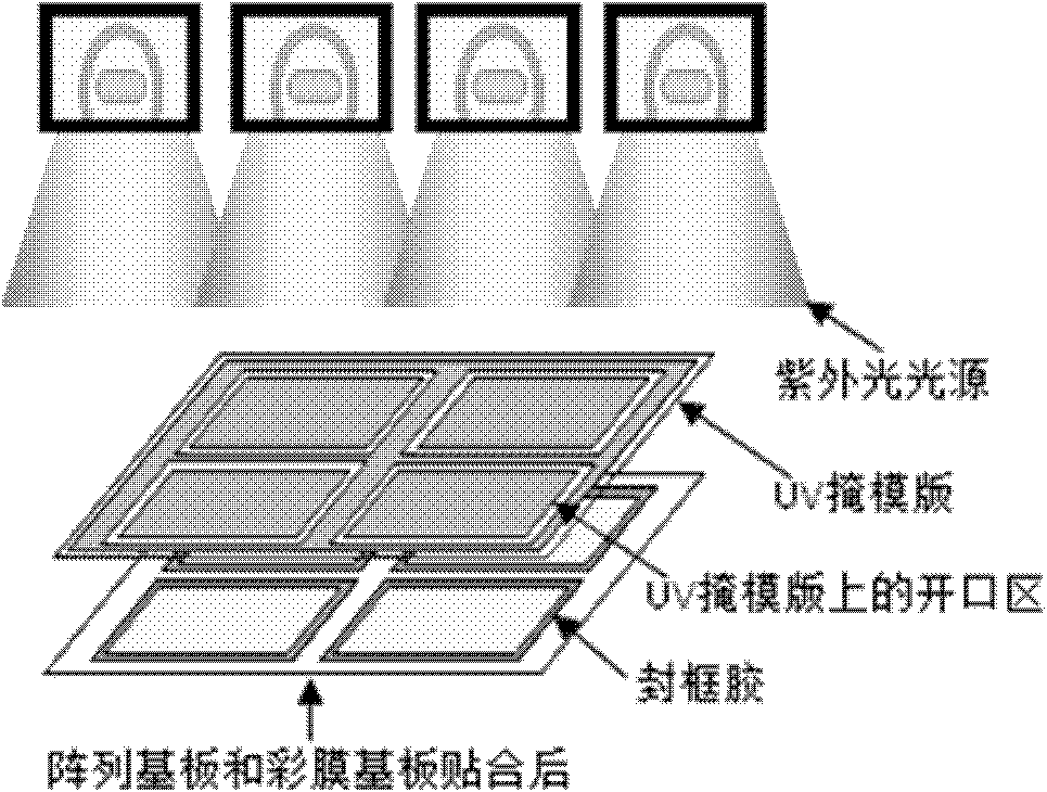
[0023] Such as Image 6 As shown, arc-shaped protrusion patterns with a certain distance are set on both sides of the sealant coating area at the four corners of the LCD screen, and the inner distance between the pair of protrusion patterns is greater than or equal to the distance between the array substrate and the color filter substrate. The width of the extended sealant, the centerline of the inner spacing of the pair of protrusions coincides with the centerline when the


PUM

PropertyMeasurementUnit
Widthaaaaaaaaaa

Abstract

The invention discloses a liquid crystal display device, which comprises an array substrate and a color film substrate opposing each other. Frame sealing adhesive is coated on the array substrate and the color film substrate, and arc protrusion patterns are arranged on two sides of each frame sealing adhesive coating area at four corners of the liquid crystal screen. The arc protrusion patterns at certain intervals are arranged on two sides of each frame sealing adhesive coating area at four corners of the liquid crystal screen to limit shape and position of the frame sealing adhesive patterns at the corners, pollution of liquid crystal by the frame sealing adhesive caused by defective hardening due to the fact that the bonded frame sealing adhesive patterns at the corners beyond a UV (ultraviolet) masking plate open area is avoided, and defective display problems such as incomplete images and the like caused by liquid crystal pollution can be reduced greatly.

Description


Claims


Application Information

Patent Timeline
Owner NANJING CEC PANDA LCD TECH
Why Eureka
Try Eureka