Display panel, display device, and electronic unit
A display panel and display device technology, applied in electrical components, static indicators, optics, etc., can solve problems such as barrier layer corrosion, and achieve the effect of preventing structure from being electrified or corroded
Active Publication Date: 2012-10-17
JAPAN DISPLAY INC
View PDF10 Cites 4 Cited by
- Summary
- Abstract
- Description
- Claims
- Application Information
AI Technical Summary
Problems solved by technology
[0006] However, such construction of the barrier layer with metal will cause the following disadvantages: as long as water enters the display panel from the external environment, the barrier layer wi
Method used
View moreImage
Smart ImageViewing Examples

Examples
no. 1 example
[0035] 1. First Embodiment (Liquid Crystal Display Device)
[0036] 2. Second Embodiment (Organic Electro-Luminescence (EL) Display Device)
Login to view more PUM
 Abstract
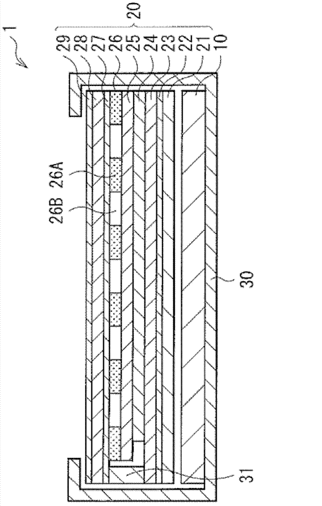
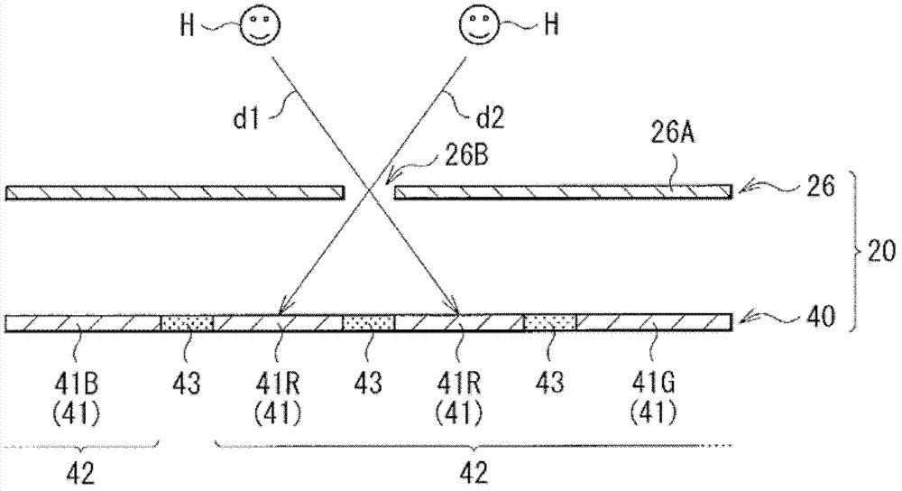
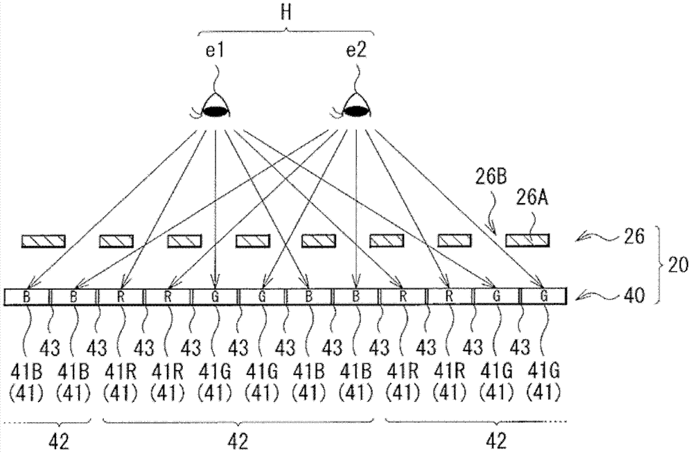
There are provided a display panel being both anti-static and resistant to corrosion, a display device provided with the display panel, and an electronic unit provided with the display device. The display panel includes a panel section including a plurality of pixels arranged in a matrix; a barrier layer provided at an upper or lower part of the panel section, and the barrier layer including light-shielding regions and transmissive regions that are arranged systematically; and a transparent conductive layer provided at the upper part of the panel section.
Description
Login to view more Claims
Login to view more Application Information
Patent Timeline
 Owner JAPAN DISPLAY INC
- R&D Engineer
- R&D Manager
- IP Professional
Why Eureka
- Industry Leading Data Capabilities
- Powerful AI technology
- Patent DNA Extraction
Try Eureka
Browse by: Latest US Patents, China's latest patents, Technical Efficacy Thesaurus, Application Domain, Technology Topic.
© 2024 PatSnap. All rights reserved.Legal|Privacy policy|Modern Slavery Act Transparency Statement|Sitemap