System for relieving scorification of convection heated surface of boiler

A slagging and boiler technology, applied in the direction of lighting and heating equipment, to achieve the effect of increasing operating time, reducing impact and improving efficiency

Active Publication Date: 2012-11-28
DONGFANG ELECTRIC CORP LTD
View PDF7 Cites 3 Cited by
  • Summary
  • Abstract
  • Description
  • Claims
  • Application Information

AI Technical Summary

Benefits of technology

In this new design for use at higher temperatures than traditional designs used in steam generators (the temperature range being considered), there are technical improvements such as prevention or minimization of slags from sticking onto the surfaces inside the generator's tubes during startup after shutdown due to excessive accumulation overtime caused by heavy ash buildup. Additionally, it includes an integrated mechanism for removing residual material efficiently while maintaining good thermal contact between the inner walls of the vessel and external equipment. Overall, these innovations improve the performance and lifespan of conventional steam generating systems compared to older models.

Problems solved by technology

This patents discusses different methods or techniques aimed towards reducing slags from boiling systems (BFS) containing fossils mixed together. These technical solutions include controlling the fuel injection parameters based upon specific criteria like sludgeiness index, ignition timing margin, etc., optimizing the use of fuels while minimizing environmental concerns associated with them. Additionally, proposing ways to mitigate sulfur oxidation issues without causing damage to other components within the system itself.

Method used


Image

  • System for relieving scorification of convection heated surface of boiler

Examples


Embodiment Construction

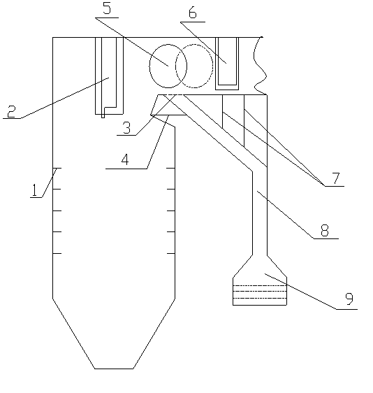
[0024] Such as figure 1 As shown, a system for alleviating slagging on the convective heating surface of a boiler includes a slagging device 5 arranged in the boiler flue, and the slagging device 5 is located at the windward front end of the convective superheater 6 at the top of the flue. The slag container 5 includes two symmetrically arranged disks and a straight pipe fixedly arranged between the disks, and the slag container 5 can roll along the axial direction of the flue.

[0025] The flue where the slag condenser 5 and the convection superheater 6 are located is arranged horizontally.

[0026] The part of the flue corresponding to the lower end of the slag condenser 5 is provided with a slag discharge port, and the lower end of the slag discharge port is provided with a slag conveying pipe 8, which is connected to the slag pool 9; Transport to the slag pool 9.

[0027] The slag discharge port is provided with a movable slag discharge baffle 3, which can be opened during


PUM


Abstract

The invention relates to a technology for relieving scorification of a convection heated surface of a boiler, in particular to a system for relieving scorification of the convection heated surface of a boiler. The system comprises a crust block machine arranged in a flue of a boiler, wherein the crust block machine is positioned at the front end of the windward side of a convection superheater at the top of the flue; the crust block machine comprises two symmetrically arranged disks and a straight pipe fixedly arranged between the two disks; and the crust block machine can roll in the axial direction of the flue. The crust block machine is applicable to various boilers using high-alkali metal content coal; scorification can be made in advance; safe operation of the convection heated surface is ensured; the operation time of the boiler is increased; offset of smoke temperature at a hearth outlet and uneven flow field caused by combustion of a quadrangle tangent circle boiler are reduced by the arrangement of the crust block machine; frequent explosion of the convection superheater and the reheater is avoided; normal operation of the boiler is not affected in the process of slag removal and scorification cleaning; the operation time of the boiler is prolonged; and the economical efficiency of a power plant is improved.

Description


Claims


Application Information

Patent Timeline
Owner DONGFANG ELECTRIC CORP LTD
Why Eureka
Try Eureka