Method for producing a light-radiating surface and a lighting device for implementing the method

A light-emitting device and a technology of light radiation, applied in the field of light-emitting, can solve the problems of light-flow intensity reduction, light-flow loss, lack of surface brightness of light-radiating surfaces, and devices with smooth illumination colors, so as to enhance processing capacity and increase uniformity Effect

Inactive Publication Date: 2013-04-03
OBSHCHESTVO S OGRANICHENNOJ OTVETABTVENNOSTJU DIS PLJUS
View PDF7 Cites 0 Cited by
  • Summary
  • Abstract
  • Description
  • Claims
  • Application Information

AI Technical Summary

Problems solved by technology

[0014] The disadvantage of the known device of this kind is the loss of the light flux emitted laterally from the optical axis by the light-emitting diodes, and the non-uniform exit angle of the light-radiating surface due to the fact that when combined with Decrease in the intensity of the light flux incident on the illuminated area as the distance from the optical axis of the illuminated area increases and due to the lack of means for smoothing the surface brightness of the light-radiating surface and the color of the illumination

Method used


Image

  • Method for producing a light-radiating surface and a lighting device for implementing the method
  • Method for producing a light-radiating surface and a lighting device for implementing the method
  • Method for producing a light-radiating surface and a lighting device for implementing the method

Examples


Example Embodiment

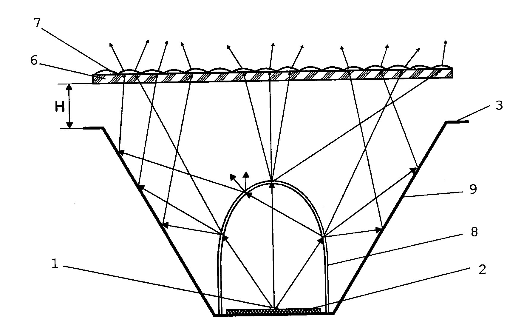
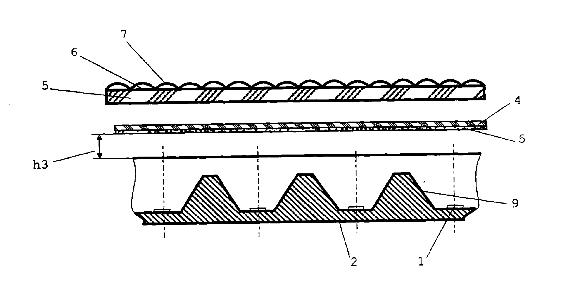
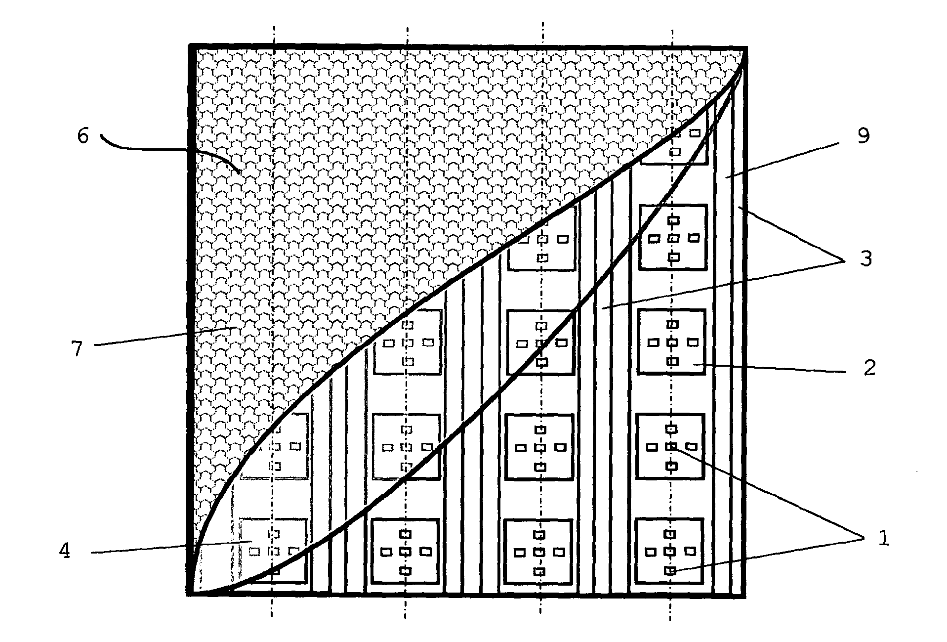
[0050] lighting equipment ( figure 1 ) comprising: a light-emitting diode (LED) emitter 1 located on a panel 2; a light-reflecting structure 3; a planar substrate 4 located at a distance h1 from the light-reflecting structure 3 and equipped with first means for transforming radiation, which One means is in the form of luminophore particles 5 applied to the surface of the substrate 4; a second means for converting radiation is a plate 6 located at a distance h2 from the planar substrate and equipped with a patterned surface 7 form.

[0051] lighting equipment ( figure 2 ) comprising: a light-emitting diode (LED) emitter 1 located on a panel 2; first means for converting radiation, which are luminophore particles 5 contained in the material of a three-dimensional substrate 8 (in figure 2 not shown in ), the substrate 8 covers the light-emitting diode light source 1; the light-reflecting structure 3; the second device for transforming the radiation is a patterned Surface 7 in t


PUM


Abstract

A method for producing a light-radiating surface and a lighting device for implementing the method relate to lighting technology, specifically to LED lighting devices which are intended for producing external and internal lighting. The method for producing a light-radiating surface comprises operations for generating a stream of radiation; establishing the direction of flow of a light-reflecting structure; irradiating luminophore particles forming a first means for transforming the stream of radiation; and using a stream of light to irradiate a second means for transforming the stream of radiation, which means is produced from an optically transparent material and is equipped with scattering means. The lighting device comprises a radiation source in the blue and/or ultraviolet range of the spectrum; a first means for transforming the radiation, which means is equipped with luminophore particles; a light-reflecting structure which can change the radiation direction; and a second means for transforming the radiation, which means is equipped with light-scattering elements, is constructed from an optically transparent material and has a light-radiating surface.

Description


Claims


Application Information

Patent Timeline
Owner OBSHCHESTVO S OGRANICHENNOJ OTVETABTVENNOSTJU DIS PLJUS
Why Eureka
Try Eureka