Clamp-free transformer winding and binding method thereof

A transformer winding and transformer technology, applied in the direction of transformer/inductor coil/winding/connection, coil manufacturing, etc., can solve the problem of not being able to press the coil with upper and lower clamps, so as to enhance the ability to resist short circuit and prevent displacement and deformation. Effect

Active Publication Date: 2013-04-17
WUJIANG TRANSFORMER
View PDF6 Cites 3 Cited by
  • Summary
  • Abstract
  • Description
  • Claims
  • Application Information

AI Technical Summary

Benefits of technology

This new design uses two parts - one part called an integrating member that holds both high-voltage and lower voltages on it while another part called a support plate helps keep them securely attached together during use. By combining these components into this single unit with cables ties or other means like wires, they can prevent any movement from affecting their function properly. Overall, this innovation improves the performance and durability of electrical devices such as transformers used at different stages throughout production.

Problems solved by technology

This patented technical problem addressed in this patents relates to improving the design for an insulated wire (IW) windings used in power systems such as voltage converters due to its high potential risk during faults like surges. Specifically, there has been research conducted into preventing these types of failures from happening more frequently than usual because they may lead to catastrophic failure if any significant excess energy flows through them beforehand.

Method used


Image

  • Clamp-free transformer winding and binding method thereof
  • Clamp-free transformer winding and binding method thereof

Examples


Embodiment

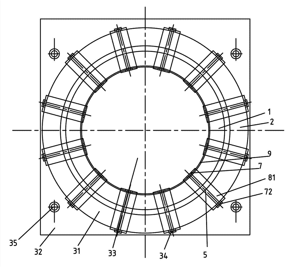
[0024] Refer to attached figure 1 ,Such as figure 2 As shown, a transformer winding without clips includes a coil with a hollow hole 11, a pressure plate 3 arranged on the upper part of the coil, and a supporting plate 4 arranged on the lower part of the coil. The pressing plate 3 and the supporting plate 4 are respectively set There are a first upper hole 33 and a first lower hole 43 corresponding to the hollow hole 11 of the coil, and the transformer winding also includes a plurality of cable ties 5 passing through the pressure plate 3 and the supporting plate 4 to tighten the coil. 5 are separately arranged along the circumferential direction of the coil.

[0025] The pressing plate 3 has a first upper portion 31 covering the coil and a second upper portion 32 extending out of the coil, the supporting plate 4 has a first lower portion 41 covering the coil and a second lower portion 42 extending out of the coil, the second lower portion 42 of the pressing plate 3 The s


PUM


Abstract

The invention relates to a clamp-free transformer winding and a binding method thereof. The clamp-free transformer winding comprises a coil with a hollow hole, a pressure plate arranged on the upper portion of the coil and a support plate arranged on the lower portion of the coil. The pressure plate and the support plate are provided with a first upper hole and a first lower hole corresponding to the hollow hole of the coil respectively. The transformer winding further comprises a plurality of binding straps which penetrate through the pressure plate and the support plate to tightly bind the coil, and the binding straps are separately distributed along the circumference of the coil. The clamp-free transformer winding can avoid coil displacement and deformation and is high in short-circuit resistance.

Description


Claims


Application Information

Patent Timeline
Owner WUJIANG TRANSFORMER
Why Eureka
Try Eureka