Device for changing laser transmission characteristics by utilizing photo-thermal effect

A technology of transmission characteristics and photothermal effect, applied in optics, optical components, instruments, etc., can solve problems such as beam distortion, and achieve the effects of low cost, wide spectral response range and high reliability

Inactive Publication Date: 2013-05-01
CHANGCHUN INST OF OPTICS FINE MECHANICS & PHYSICS CHINESE ACAD OF SCI
View PDF4 Cites 4 Cited by
  • Summary
  • Abstract
  • Description
  • Claims
  • Application Information

AI Technical Summary

Problems solved by technology

[0005] In order to solve the beam distortion correction problem in the existing strong laser system, the present

Method used


Image

  • Device for changing laser transmission characteristics by utilizing photo-thermal effect
  • Device for changing laser transmission characteristics by utilizing photo-thermal effect

Examples


specific Embodiment approach 1

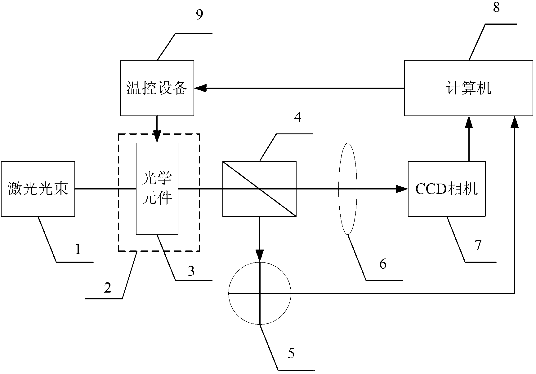
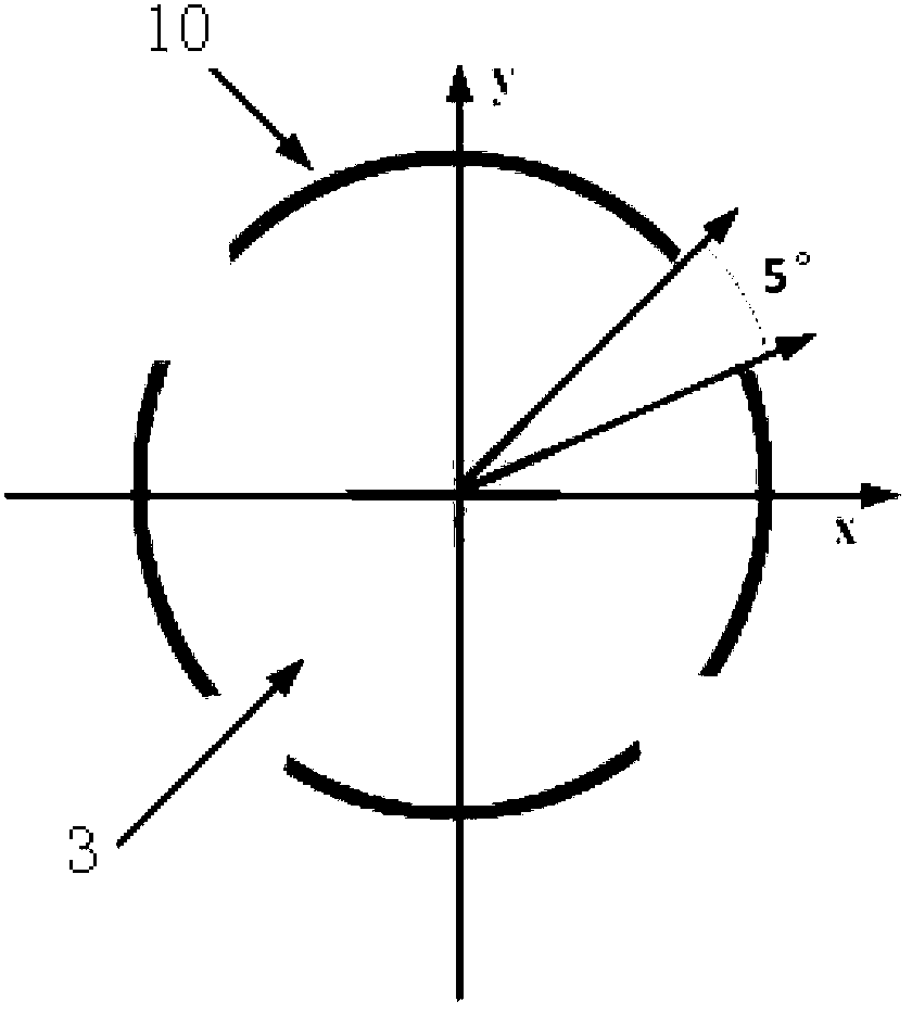
[0011] Specific implementation mode 1. Combination figure 1 and figure 2 Describe this embodiment, a device that uses the photothermal effect to change the laser transmission characteristics. The laser beam 1 emits a laser beam with a wavefront laser and enters a vacuum box 2 with a laser window. The purpose of the vacuum box 2 is to prevent the ring heater from The heating of the nearby air creates convection, which causes localized turbulence and introduces additional beam wavefront distortion. Then the beam passes through the transmission optical element 3 of the ring heater, and the corrected laser beam is divided into two beams by the beam splitter 4, one of which is monitored by the four-quadrant detector 5, and the other beam is focused on the CCD camera 7 by the lens 6 , the CCD camera 7 can move back and forth, and the wavefront information of the light beam can be restored by obtaining multiple spot images on the defocus plane and the focal plane. The temperature con


PUM


Abstract

The invention discloses a device for changing laser transmission characteristics by utilizing a photo-thermal effect, and relates to the field of laser beam quality control. The problem of beam distortion correction in the conventional intense laser system is solved. The device comprises a ring heater, an optical element, a vacuum chamber, a beam splitter, a lens, temperature control equipment, a charge-coupled device (CCD) camera and a four-quadrant detector, wherein the optical element with the ring heater is arranged in the vacuum chamber with a laser window; a laser beam is split into two paths of beams by the beam splitter after passing through the optical element with the ring heater, one path of beam is received by the four-quadrant detector, and the other path of beam is imaged on the CCD camera after being focused by the lens; a computer solves the imaging information of the CCD camera, and transmits the solved imaging information to the temperature control equipment; and the temperature control equipment performs temperature control on the ring heater according to the received information. The device can be used for the correction of wave front distortion of lasers with various wavelengths.

Description


Claims


Application Information

Patent Timeline
Owner CHANGCHUN INST OF OPTICS FINE MECHANICS & PHYSICS CHINESE ACAD OF SCI
Why Eureka
Try Eureka