Radial heat tube-ordinary heat exchange tube combined type waste heat recovery device for flue tail gases

A technology of waste heat recovery device and radial heat pipe, which is applied in the steam generation method using heat carrier, etc., can solve the problems such as the reduction of heat exchange efficiency, and achieve the effects of improving heat utilization rate, avoiding dew point corrosion, and high heat exchange efficiency

Inactive Publication Date: 2013-09-11
ACRE COKING & REFRACTORY ENG CONSULTING CORP +1
View PDF8 Cites 6 Cited by
  • Summary
  • Abstract
  • Description
  • Claims
  • Application Information

AI Technical Summary

Benefits of technology

In this design that combines two types of materials - one material acts like an insulator while another material works with it's own properties (like conductivity). When there is condensation on certain parts or surfaces within these systems, they become electrically charged due to static electricity generated by friction between them during operation. These charges attract small particles from other areas creating tiny holes called “cavities” along their surface. If any charge remains after several hours without being removed, then some atoms form new ones when exposed again causing damage if reused later. By combining both materials together, we aim to solve problems such as deteriorated durability caused by moisture buildup and potential electrostatic discharge issues associated with common methods involving metal-based coatings.

Problems solved by technology

This patented technical solution described in the patents describes how different types of devices can help remove unwanted materials like harmful gases or liquids during combustion processes such as coal burning. These solutions involve using specialized heat exchangers called finset tube thermal recovery systems, where certain parts inside them work together efficiently without consuming too much power compared to traditional methods involving only one unit per kiloace. However, these existing designs have drawbacks including poor reliability due to issues related to sulfur contamination and potential damage caused when exposed to acid rain.

Method used


Image

  • Radial heat tube-ordinary heat exchange tube combined type waste heat recovery device for flue tail gases
  • Radial heat tube-ordinary heat exchange tube combined type waste heat recovery device for flue tail gases
  • Radial heat tube-ordinary heat exchange tube combined type waste heat recovery device for flue tail gases

Examples


Embodiment Construction

[0029] The present invention will be further described below in conjunction with accompanying drawing.

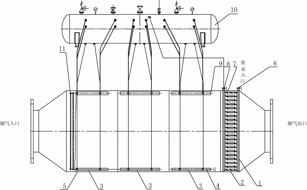
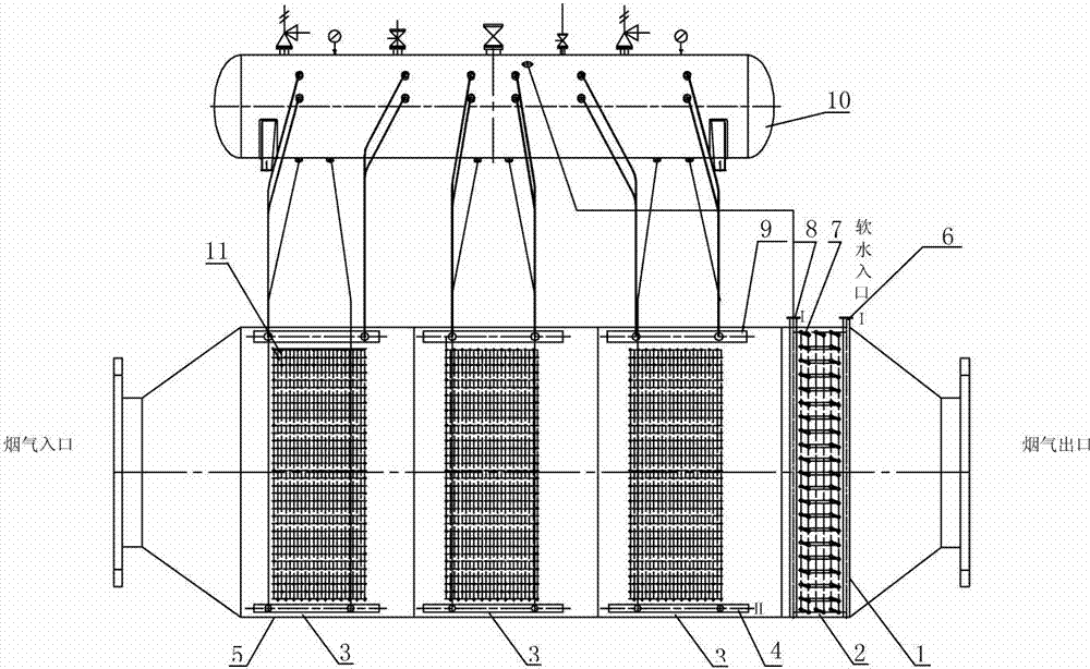
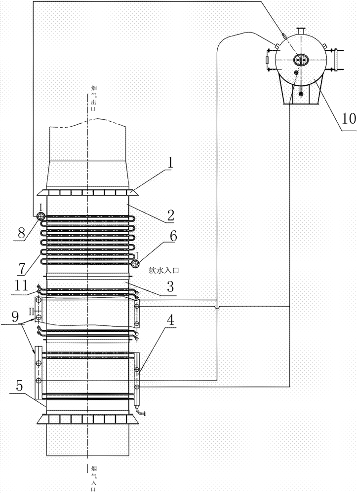
[0030] Such as figure 1 , figure 2 , image 3 with Figure 4 As shown, the radial heat pipe-ordinary heat exchange tube combined waste heat recovery device for flue tail gas of the present invention includes a gas box 1 and a heat exchange device arranged in the gas box 1, and is characterized in that:

[0031] The side plate of the gas box 1 is a tube plate 5, and a through hole is opened on the tube plate 5. The two ends of the gas box 1 are respectively a flue gas inlet and a flue gas outlet. The upper part of the casing 1 is provided with a steam-water separator 10,

[0032] The heat exchange device of the present invention is composed of a preheating heat exchange tube group 2 and an evaporation heat exchange tube group 3,

[0033] The preheating heat exchange tube group 2 is composed of a radial heat pipe 7 and an inlet header I6 and an outlet header I8 connected


PUM


Abstract

The invention discloses a radial heat tube-ordinary heat exchange tube combined type waste heat recovery device for flue tail gases. The waste heat recovery device comprises a gas box body and a heat exchange device which is arranged inside the gas box body. The waste heat recovery device is characterized in that side plates of the gas box body are tube plates, through-holes are formed in the tube plates, a flue gas inlet and a flue gas outlet are arranged at two ends of the gas box body respectively, a steam-water separator is arranged on the upper portion of the box body, the heat exchange device is composed of a preheating heat exchange tube group and evaporating heat exchange tube groups, the preheating heat exchange tube group is composed of a radial heat tube and a water inlet header and a water outlet header I which are connected with the radial heat tube, and the evaporating heat exchange tube groups are composed of ordinary heat exchange tubes, water inlet headers II and steam outlet boxes. The waste heat recovery device has the advantages that the combined type waste heat recovery device in the structure is used in flue gas discharging, heat of flue exhaust gases is transferred to soft water through heat transfer by the radial heat tube, and steam is produced, so that the exhaust gas temperature of the flue tail gases is reduced, the heat utilization ratio is improved, and the dew point corrosion can be effectively avoided.

Description


Claims


Application Information

Patent Timeline
Owner ACRE COKING & REFRACTORY ENG CONSULTING CORP
Why Eureka
Try Eureka