Gigging fuse wire structure

A fused filament structure and raising technology, applied in filament/thread forming, textile and papermaking, fiber processing, etc., can solve the problems of chemical fiber insulation performance is not good, excellent, chemical fiber does not have natural fiber uneven texture, etc., to prevent Air flow, the effect of improving thermal insulation performance

Inactive Publication Date: 2013-11-27
SUZHOU HAOJIAN TEXTILE
View PDF9 Cites 1 Cited by
  • Summary
  • Abstract
  • Description
  • Claims
  • Application Information

AI Technical Summary

Benefits of technology

The invention relates to an improved type of fusible link used for electrical circuits that has several technical benefits: it allows more efficient transferring power without causing excessive temperature increase or reducing efficiency; creates tiny bubbles inside the molten material when melting due to its expandability, preventing any unwanted movement caused by external pressure such as winds or rainwater during operation. This results in better energy savings over time compared to traditional methods like welded connections.

Problems solved by technology

This patented technical problem addressed in the patents relates to improving the quality of chemically bondable yarn products while maintaining flexibility with regards to manufacturing processes like weaving machines during production.

Method used


Image

  • Gigging fuse wire structure
  • Gigging fuse wire structure
  • Gigging fuse wire structure

Examples


Embodiment 1

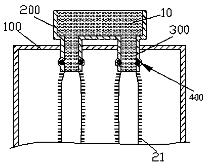
[0018] refer to figure 1 , in this embodiment, the fleece fuse structure includes a melt extrusion device 200 filled with melt 10 and a fuse nozzle 300 arranged on the melt extrusion device 200, and the fuse nozzle 300 nozzle It is arranged downward on the top of a closed box 100, and the inner surface of the fuse nozzle 300 is provided with a heat conduction layer, and the heat conduction layer is thermally connected with a cooling device, and the inner surface of the fuse nozzle 300 is evenly distributed along the circumferential direction. There is a perforating member 400 for perforating the melt 10 .

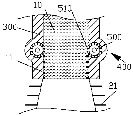
[0019] refer to figure 2 , the perforating member 400 is a pulley 500 ring-distributed in the inner wall of the fuse nozzle 300, the wheel surface side of the pulley 500 is tangent to the melt 10, the wheel surface of the pulley 500 is uniform A thin column 510 with a cooling layer on the top is arranged, and the pulley 500 rotates synchronously with the movement of the mel

Embodiment 2

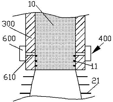
[0025] refer to figure 1 with image 3 , in this embodiment, only the perforating member 400 of the first embodiment is transformed into a nozzle 610 distributed on the inner wall of the fuse nozzle 300, and the nozzle 610 is connected with an intermittent pumping device 600 connected.

[0026] The working principle and method of the above-mentioned fleece fuse structure:

[0027] refer to figure 1 with image 3 , the melt 10 forms a small hole 11 due to the intermittent gas ejected from the spout 610, and the melt 10 forms a solidified layer with the small hole 11 due to the cooling of the heat conduction layer, and the melt 10 The expansion phenomenon, the melt 10 bound by the solidified layer expands, and flows out from the small hole 11 to form fluff 21 .


PUM


Abstract

The invention provides a gigging fuse wire structure which comprises a fuse element extrusion device filled with a fuse element and a fuse wire nozzle arranged on the fuse element extrusion device, wherein a spout of the fuse wire nozzle is downwards formed in the top of a closed box body; a heat conduction layer is arranged on the inner surface of the fuse wire nozzle and is in heat connection with a cooling device; punching members punching the fuse element are arranged on the inner surface of the fuse wire nozzle circumferentially and uniformly. According to the gigging fuse wire structure, by the aid of the cooling of the heat conduction layer and the action of the punching members, a solidification layer with small holes is arranged outside the structure; and the solidified and restrained fuse element expands due to a swelling phenomenon of the fuse element and flows out from the small holes, and fluffs are formed.

Description


Claims


Application Information

Patent Timeline
Owner SUZHOU HAOJIAN TEXTILE
Why Eureka
Try Eureka