DC-DC converter

A DC-DC and converter technology, applied in the field of DC-DC converters, can solve problems such as limiting the output voltage drop speed, and achieve low power consumption, simple structure, and easy implementation

Inactive Publication Date: 2014-01-01
UNIV OF ELECTRONICS SCI & TECH OF CHINA
View PDF4 Cites 11 Cited by
  • Summary
  • Abstract
  • Description
  • Claims
  • Application Information

AI Technical Summary

Benefits of technology

This technology allows filters without changing their input voltages can maintain stable performance even at high speeds by allowing them to work more efficiently over different frequencies or operating modes. It also eliminates any issues caused by changes made on other components such as inductors due to temperature variations affecting its operation. Overall, this innovation simplifies design and reduces energy usage while still providing effective filtering capabilities.

Problems solved by technology

This patented technical problem addressed in this patents relates to improving the performance characteristics of small step response regulators while reducing their overall power dissipations during rapid changes in input voltages. Specifically, traditional methods involve slow down or increase the charge capacity of certain components within these systems due to faster transitions from one mode to another mode. However, they also lead to lowered efficiencies caused by overlapping oscillating frequencies. To address this issue, new techniques like synchronized pulse width modulated (SPM), multiphase delta sigma-delta (MDS)-PWM, etc., were developed to improve the responsiveness and decrease power consumptions without compromising linearity requirements. These improvements aim to achieve better performance levels despite slower changing rates.

Method used


Image

  • DC-DC converter
  • DC-DC converter
  • DC-DC converter

Examples


Embodiment Construction

[0022] Below in conjunction with accompanying drawing, describe technical scheme of the present invention in detail:

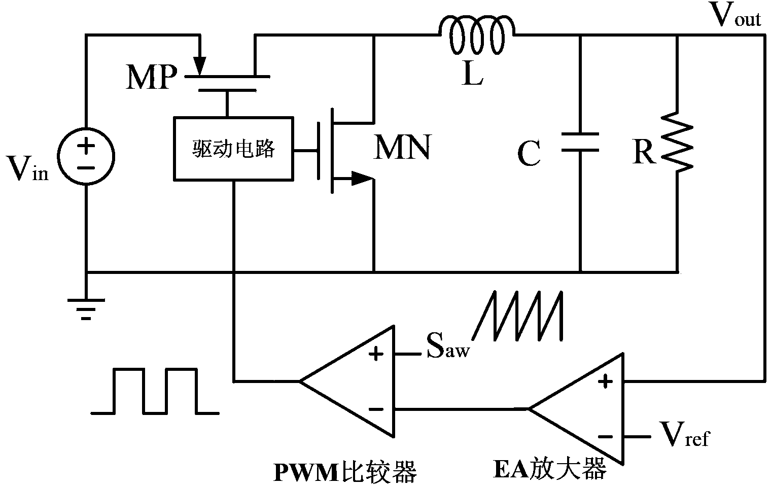
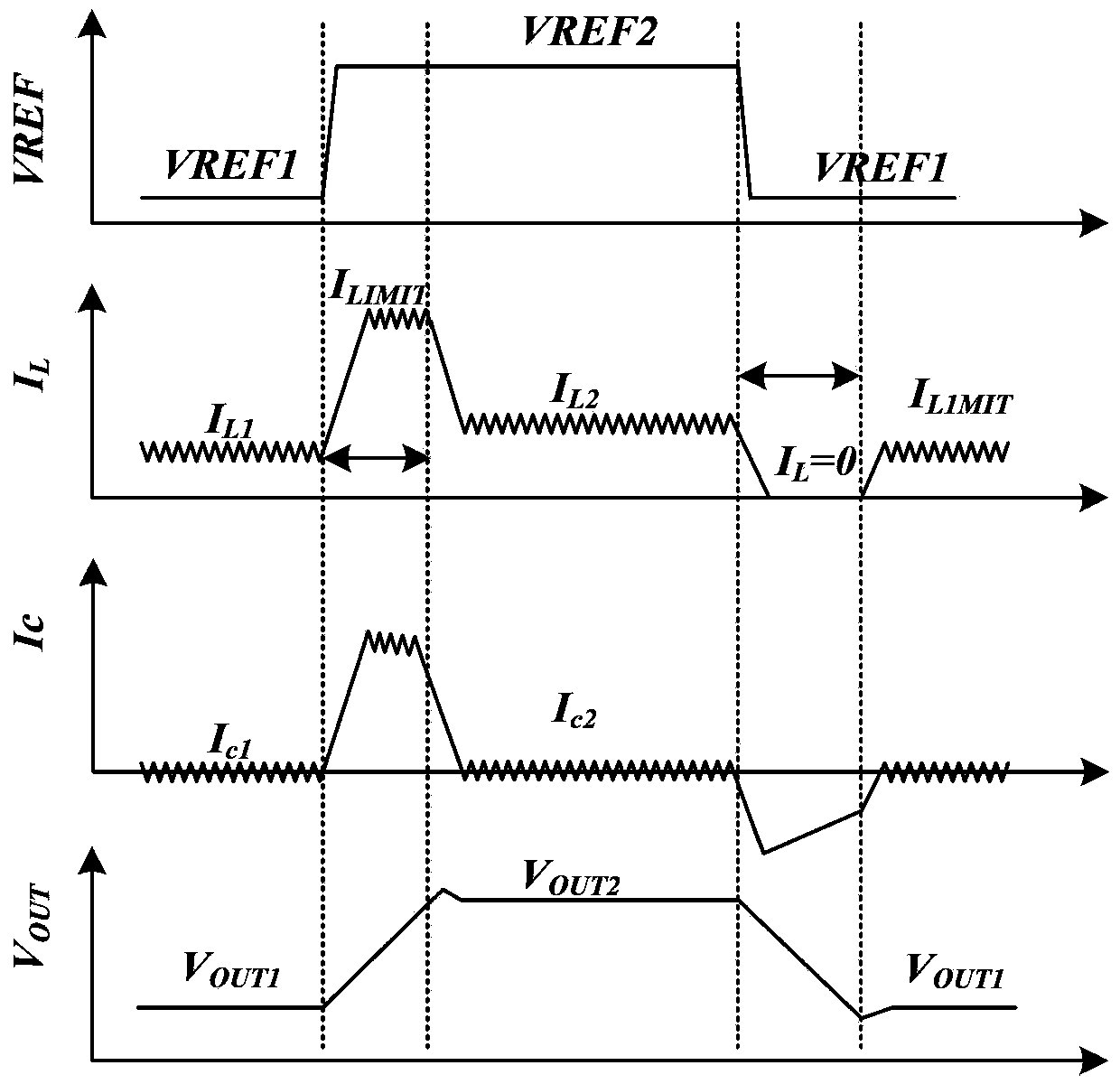
[0023] Such as figure 1 As mentioned above, it is a basic frame structure of a traditional DC-DC converter. right figure 1 The schematic diagram of the DC-DC converter for output voltage regulation is shown in figure 2 shown. When the DC-DC converter adjusts the output voltage rise process, the reference voltage rises rapidly, so that the PWM comparator outputs a square wave signal with a large duty cycle, and the power transistor MP is turned on for a long time through the drive circuit, causing the inductor current to rise rapidly. After the inductor current exceeds the value set by the current limiting module, the inductor current changes around the current limiting value. In this process, the inductor current charges the capacitor with the maximum current, so that the output voltage rises rapidly until the output voltage is equal to the reference voltage


PUM


Abstract

The invention relates to the technology of a power source and an integrated circuit, in particular to a DC-DC converter with the output voltages capable of being adjusted quickly. The DC-DC converter comprises a driving circuit, a PMOS tube MP, an NMOS tube MN, a PWM comparator, an EA amplifier, an inductor L, a capacitor C, a resistor R and a power source Vin. The DC-DC converter is characterized in that a calculating amplifier is further included, the driving circuit, the PMOS tube MP, the NMOS tube MN, the PWM comparator, the EA amplifier, the inductor L, the capacitor C, the resistor R and the power source Vin form a traditional DC-DC converter, and the positive input end and the output end of the calculating amplifier are connected to be used as one end, connected to the capacitor C, of a bumper. The DC-DC converter has the advantages of being simple in structure, easy to achieve, low in power consumption, and capable of achieving quick adjusting of the output voltages of the DC-DC converter only by small domain area. The DC-DC converter is particularly suitable for DC-DC converters.

Description


Claims


Application Information

Patent Timeline
Owner UNIV OF ELECTRONICS SCI & TECH OF CHINA
Why Eureka
Try Eureka