Powerful gas circulating and stirring device of vacuum induction sintering furnace

A vacuum induction furnace, vacuum induction technology, applied in the direction of stirring device, furnace, furnace components, etc., to achieve the effect of reducing energy consumption, increasing productivity, and improving the firing pass rate

Active Publication Date: 2014-01-29
SHENYANG STARLIGHT ADVANCED CERAMICS
View PDF6 Cites 0 Cited by
  • Summary
  • Abstract
  • Description
  • Claims
  • Application Information

AI Technical Summary

Problems solved by technology

None of the above situations is a good solution

Method used


Image

  • Powerful gas circulating and stirring device of vacuum induction sintering furnace

Examples


Embodiment Construction

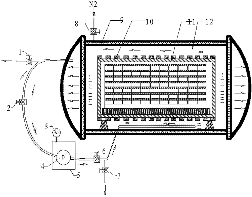
[0012] The vacuum induction sintering furnace gas strong circulation stirring device includes a vacuum induction furnace body 9, an induction heating body 11 arranged in the vacuum induction furnace body, an induction coil 10 wrapped around the induction heating body, a vacuum vortex fan 4, and a closed box body 5 and vacuum valve. The vacuum induction furnace body 9 is provided with a vacuum vortex blower 4 that strongly stirs the gas, and is connected to the rear and front of the vacuum induction furnace body 9 through the inlet pipeline and the outlet pipeline connecting the vacuum vortex blower 4, and is connected to the cavity. Body 12 communicates. The inlet pipeline of the vacuum vortex fan is equipped with the first vacuum valve 1 for exhausting and the second vacuum valve 2 for air extraction control, and the outlet pipeline is equipped with the third vacuum valve 6 for air intake control and the fourth vacuum valve for venting 7 and the fifth vacuum valve 8 on the nitr


PUM


Abstract

A powerful gas circulating and stirring device of a vacuum induction sintering furnace. The powerful gas circulating and stirring device comprises a vacuum induction furnace body, an induction heating body arranged in the vacuum induction furnace body, an induction coil wound and sleeved on the induction heating body, a vacuum vortex fan, a closed box and a vacuum valve, and the vacuum vortex fan powerfully stirring gas arranged outside the vacuum induction furnace body is connected with the rear end and the front end of the vacuum induction furnace body by connecting an inlet pipeline and an outlet pipeline of the vacuum vortex fan and communicated with a cavity. The powerful gas circulating and stirring device has quite obvious effect of improving gas participation in reaction, sintering yield is increased, energy consumption is effectively lowered, loading rate is increased, pit furnace cooling time is shortened, and productivity is greatly improved.

Description


Claims


Application Information

Patent Timeline
Owner SHENYANG STARLIGHT ADVANCED CERAMICS
Why Eureka
Try Eureka