Feeder for heating bar stock of mini-tiller

A technology of feeding device and tiller, which is applied in the direction of conveyor objects, transportation and packaging, etc. It can solve the problems of unstable manual feeding frequency and uneven heating, and achieve the effect of simple structure, uniform heating and stable frequency amplitude

Inactive Publication Date: 2014-04-02
CHONGQING CHENGSHUO TECH
View PDF0 Cites 0 Cited by
  • Summary
  • Abstract
  • Description
  • Claims
  • Application Information

AI Technical Summary

Benefits of technology

This new design allows for better control over how well fluids are being treated by microwave energy during cookery compared to previous designs. It includes two positions - one where it's possible to use only one type of electromagnetic wave (usually called radio waves) while another location uses both types at once. By rotating an odd number of teeth around its own axis, there can be multiple ways to achieve different angles between them without changing their direction or orientation. These techniques help improve the efficiency of treatments such as fryers used for food production.

Problems solved by technology

The technical problem addressed in this patented text relates to improving the efficiency and consistency of producing multiple types of materials with different properties by utilizing automated methods that use thermal forming techniques. However, current processes have limitations such as manually-feeded heaters or poorly controlled material movement due to instability during transferring between components. This can lead to imprecise heat distribution which negatively impact the final products' qualities like strength.

Method used


Image

  • Feeder for heating bar stock of mini-tiller

Examples


Embodiment Construction

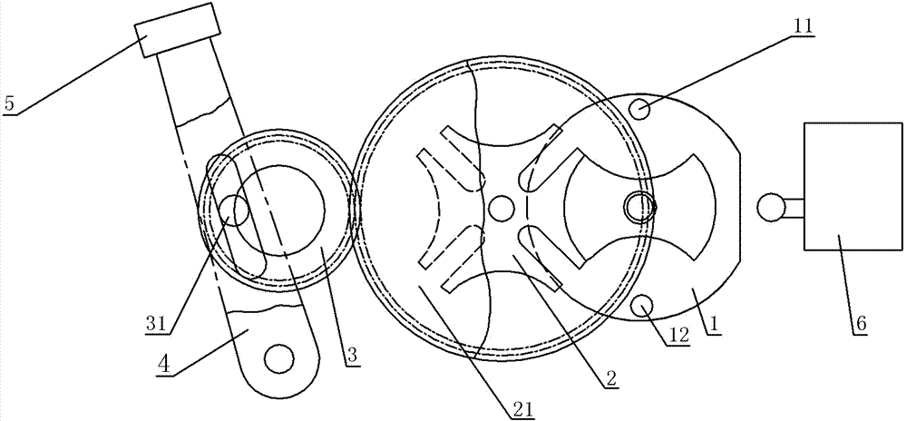
[0009] according to figure 1 As shown, the feeding device for bar heating of the tiller in the embodiment of the present invention includes a frame, and also includes a drive plate 1 that is rotatably connected with the frame, a four-index sheave 2 that is rotatably connected with the frame, and four The indexing sheave 2 coaxially fixes the first gear 21, the guide rod 4 hinged with one end of the frame, the second gear 3 meshed with the first gear 21, and the work clamp 5 threaded with the end of the guide rod 4 away from the frame , the driving disc 1 includes a circular plate and a notched disc with two mutually symmetrical locking arcs, the circular plate includes an arc segment and a straight line segment, and the circular plate is provided with a four-index sheave 2 near the edge. The first pin 11 and the second pin 12, which are mutually symmetrical about the center of the circular plate, the four-index sheave 2 matches the notch disc, the upper edge of the second gear 3


PUM


Abstract

The invention discloses a feeder for heating a bar stock of a mini-tiller and aims to solve the problem of non-uniform heating caused by the unstable manual feeding frequency in the prior art. The feeder comprises a rack and also comprises a driving disc rotationally connected with the rack, a four indexing slot wheel rotationally connected with the rack, a first gear coaxially fixed with the four indexing slot wheel, a guide rod hinged to one end of the rack, a second gear meshed with the first gear and a work clamp connected with one end, far away from the rack, of the guide rod. The driving disc comprises a circular plate and a notch disc provided with two mutually symmetrical locking arcs; the circular plate comprises an arc section and a linear section; a first pin column and a second pin column are arranged on the position, close to the edge, of the circular plate; a third pin column is arranged at the edge of the second gear; a slideway penetrating through the guide rod is arranged in the middle of the guide rod; the third pin column slides in the slideway. A single-pole double-throw switch for controlling the rotary direction of the driving disc is arranged in the position, close to the middle of the linear section of the circular plate, on the rack. The feeder for heating the bar stock of the mini-tiller is simple in structure and strong in practicability.

Description


Claims


Application Information

Patent Timeline
Owner CHONGQING CHENGSHUO TECH
Why Eureka
Try Eureka