Steel billet testing method, device and system

A steel billet inspection and steel billet technology, applied in the field of billet inspection methods, devices and systems, can solve the problems of low inspection efficiency and labor, and achieve the effect of improving efficiency

Inactive Publication Date: 2014-04-16
WUHAN IRON & STEEL (GROUP) CORP +1
View PDF4 Cites 1 Cited by
  • Summary
  • Abstract
  • Description
  • Claims
  • Application Information

AI Technical Summary

Benefits of technology

This technology allows for efficient monitoring during manufacturing processes used to produce metal products such as bars or tubes through various techniques like X ray fluorescence analysis (XRF), atomic absorption spectroscopy, infrared imaging, magnetic resonance tomography scans, ultrasound waves, etc., which can help identify defects caused due to factors affecting product quality.

Problems solved by technology

This technical problem addressed by this patented method involves complex process for inspecting or analyzing the quality of molten metal during casting operations on an industrial scale. These procedures require human input which can be time-consuming and expensive due to high employee effort required.

Method used


Image

  • Steel billet testing method, device and system
  • Steel billet testing method, device and system
  • Steel billet testing method, device and system

Examples


Embodiment Construction

[0035] In order to make the above objects, features and advantages of the present invention more comprehensible, the present invention will be further described in detail below in conjunction with the accompanying drawings and specific embodiments.

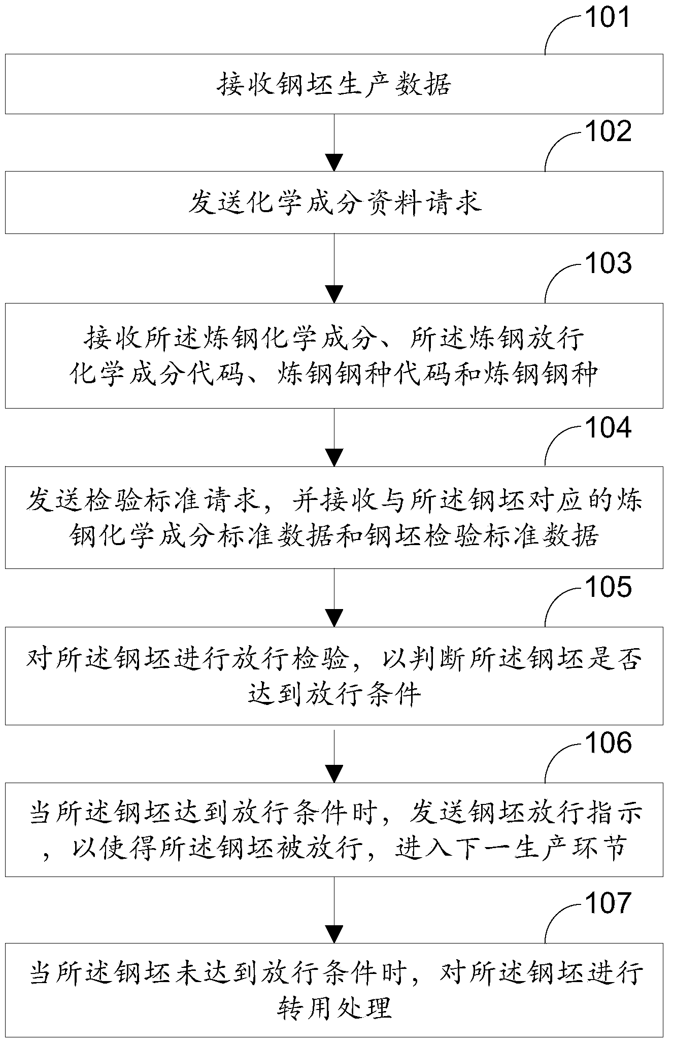
[0036] Such as figure 1 As shown, it is a flow chart of a billet inspection method provided in the embodiment of the present invention, the method includes:

[0037] Step 101, receiving billet production data;

[0038] Wherein, the billet production data includes the connecting billet mark of the billet, the T-shaped billet mark of the billet, the abnormal billet mark of the billet, the steel type code of the billet, the steel type of the billet, the The size of the steel billet, the use of the steel billet, and the whereabouts of the steel billet;

[0039] Among them, the steel billet can be divided into normal billet, connecting billet, T-shaped billet, abnormal process billet, defective billet and other types. The connecting bil


PUM


Abstract

The invention relates to the field of steel production, and discloses a steel billet testing method, device and system. The steel billet testing method includes the steps of carrying out releasing testing on steel billets according to steel billet production data, steelmaking chemical components, steelmaking releasing chemical component codes, steelmaking chemical component standard data and steel billet testing standard data so as to judge whether the steel billets meet the releasing conditions or not, when the steel billets meet the releasing conditions, sending a steel billet releasing indication to enable the steel billets to be released and enter a next production process, and when the steel billets do not meet the releasing conditions, carrying out transferring processing on the steel billets. Automatic processing of steel billet testing is achieved, and the steel billet testing efficiency is effectively improved.

Description


Claims


Application Information

Patent Timeline
Owner WUHAN IRON & STEEL (GROUP) CORP
Why Eureka
Try Eureka