Electric linear actuator

An electric actuator, linear technology, applied in the direction of transmission, sliding contact bearings, bearings of rotary motion, etc., can solve the problems of electric motor size and power consumption increase, power loss increase, etc.

Active Publication Date: 2014-09-03
NTN CORP
View PDF9 Cites 4 Cited by
  • Summary
  • Abstract
  • Description
  • Claims
  • Application Information

AI Technical Summary

Problems solved by technology

These motion converting mechanisms involve a plurality of sliding contact parts, so the loss of power

Method used


Image

  • Electric linear actuator
  • Electric linear actuator
  • Electric linear actuator

Examples


Embodiment

[0036] Preferred embodiments of the present invention will be described below with reference to the accompanying drawings.

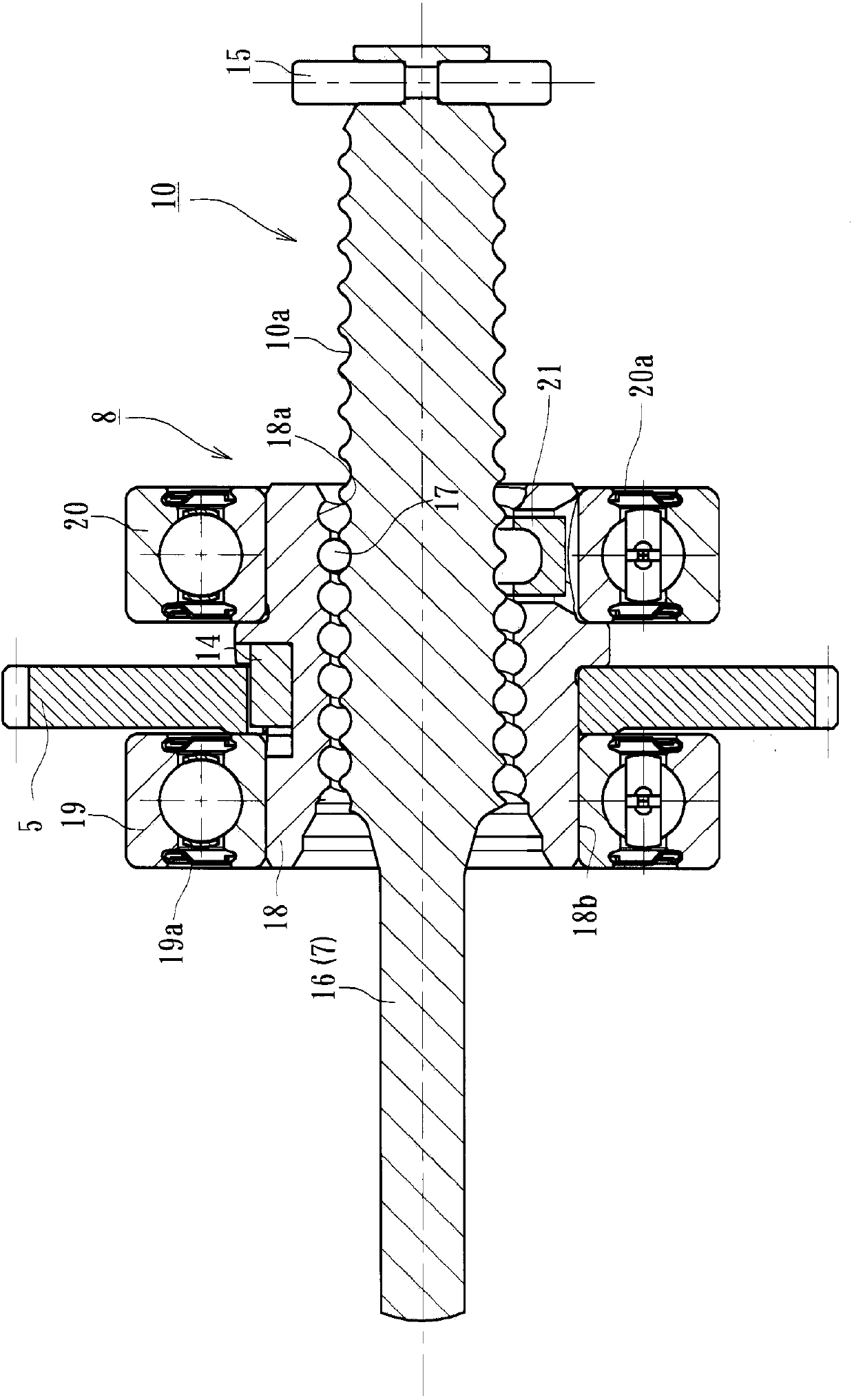
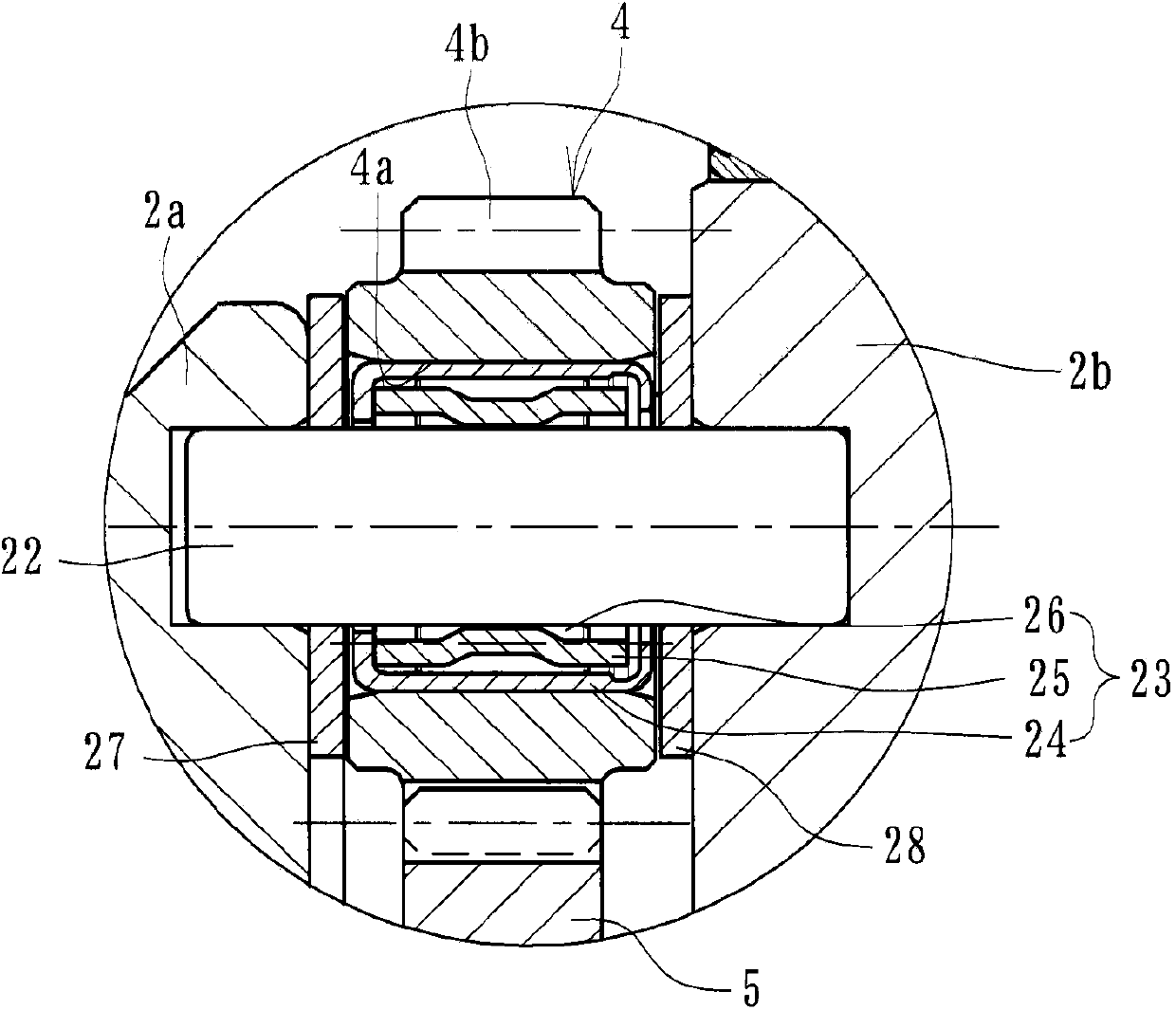
[0037] figure 1 is a longitudinal sectional view showing a preferred embodiment of the linear electric actuator of the present invention, figure 2 is shown figure 1 A longitudinal sectional view of the actuator body of the linear electric actuator, image 3 is shown figure 1 A partial enlarged view of the intermediate gear of the linear electric actuator, and Figure 4 is shown image 3 A partial enlarged view of the variant of the intermediate gear.

[0038] Such as figure 1 As shown, a linear electric actuator 1 comprises a housing 2 formed of a lightweight aluminum alloy, an electric motor (not shown), an intermediate gear mated to an input gear 3 mounted on a motor shaft (not shown) of the electric motor 4. A reduction mechanism 6 with an intermediate gear 4 and an output gear 5, a ball screw mechanism 8 that converts the rotary motion of th


PUM


Abstract

Provided is an electric linear actuator with which operation lock of a ball screw is prevented and high rotational performance is achieved at a low cost. [Solution] A housing (2) comprises a first housing (2a), and a second housing (2b). An electric motor is attached to the first housing (2a). An accommodation hole is formed at the first and second housings (2a, 2b) to accommodate a screw shaft. A deceleration mechanism (6) comprises an input gear (3) which is fixed to a motor shaft, an intermediate gear (4) which is engaged with the input shaft (3), and an output gear (5) which is engaged with the intermediate gear (4), and fixed to a nut (18) as a single unit. The intermediate gear (4) is rotatably supported via a shell-type needle bearing (23) using gear shafts (22) respectively implanted at the first housing (2a) and the second housing (2b). Ring-shaped washers (27, 28) are mounted on both sides of the intermediate gear (4). A width of a gear section of the intermediate gear (4) is configured to be smaller than a face width.

Description


Claims


Application Information

Patent Timeline
Owner NTN CORP
Why Eureka
Try Eureka