Chain tensioner

A tensioner and chain technology, applied in belts/chains/gears, mechanical equipment, transmissions, etc., can solve the problems of motor damage, easy deformation and breakage of the chain, and achieve the effect of prolonging the service life

Inactive Publication Date: 2014-11-26
ZHONGSHAN JULONG TEXTILE MACHINERY TECH
View PDF7 Cites 2 Cited by
  • Summary
  • Abstract
  • Description
  • Claims
  • Application Information

AI Technical Summary

Problems solved by technology

[0002] On the computerized flat knitting machine, one end of the chain is set on the rotating shaft of the roller, and the other end is set on the power output shaft of the motor. When the computerized flat knitting machine is working, the chain rotates under the drive of the motor, thereby driving the rotating shaft of the roller to rotate. The power output shaft, chain, and roller shaft are all made of rigid materials. If the chain is too loose, it will fall off easily. If the chain is too tight, the chain will be easily deformed or even broken after working for a period of time, which will also cause certain damage to the motor. Therefore, it is necessary to Looking for a device that can automatically adjust the tension of the chain to keep the chain in a good tension state

Method used


Image

  • Chain tensioner
  • Chain tensioner
  • Chain tensioner

Examples


Example Embodiment

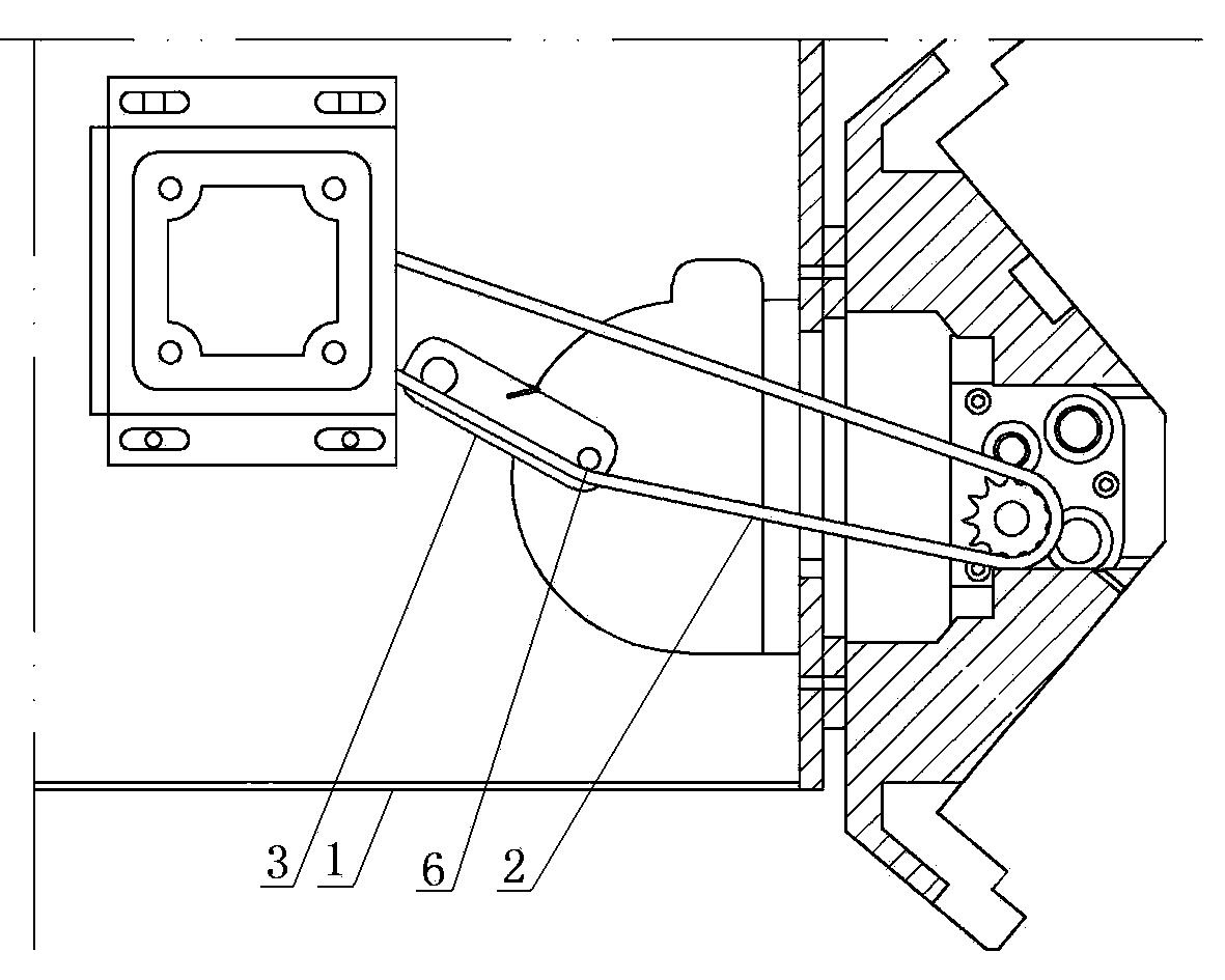
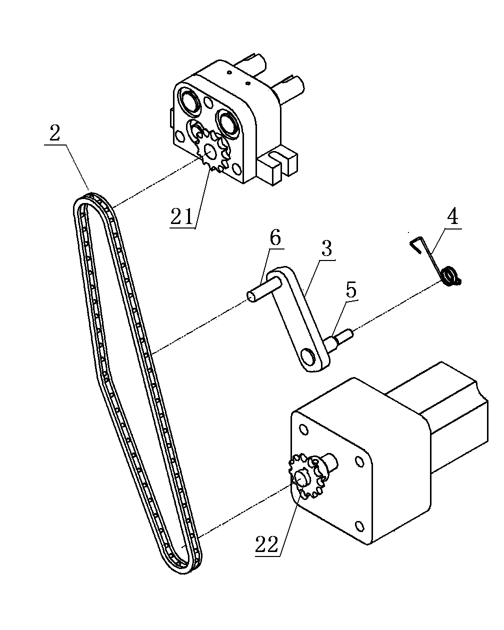
[0013] Such as figure 1 with figure 2 As shown, the chain tensioner is installed on the machine base 1 and used to adjust the tension of the chain 2. One end of the chain is sleeved on the rotating shaft 21 of the roller, and the other end is sleeved on the power output shaft 22 of the motor.

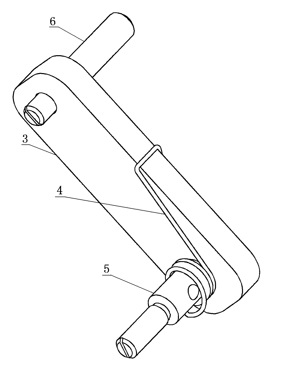
[0014] Such as image 3 As shown, the chain tensioner is mainly composed of a pendulum wall 3, a compression spring 4, a rotating shaft 5, and a compression shaft 6. The pendulum wall 3 is elongated, and both ends of the pendulum wall 3 in the length direction are semicircular shape.

[0015] The positions of the rotating shaft 5 and the pressing shaft 6 are preferably set on the center of the two semicircular ends of the pendulum wall.

[0016] The rotating shaft 5 and the pressing shaft 6 are respectively located on two opposite end surfaces of the pendulum wall 3 and are perpendicular to the pendulum wall. In order to make the pendulum wall tighter on the chain better, the end faces of the p


PUM


Abstract

The invention discloses a chain tensioner. The chain tensioner mainly consists of a swinging arm, a pressure spring, a rotating shaft and a pressing shaft. The chain tensioner is mounted on a stand for use, and is used for adjusting the tensity of a chain; and one end of the chain coats on the rotating shaft of a roller, and the other end coats on a power output shaft of a motor. The prestress of the pressure spring is preset, and the tensity of the chain is automatically adjusted through the pressure spring, so that the chain is not too tight or too loose, the service life of the chain can be prolonged, and the service life of equipment connected with the chain can be prolonged.

Description


Claims


Application Information

Patent Timeline
Owner ZHONGSHAN JULONG TEXTILE MACHINERY TECH
Why Eureka
Try Eureka