Active sound eliminator for ventilation pipeline system

A ventilation pipeline and muffler technology, which is applied in the direction of pipe components, pipes/pipe joints/pipe fittings, mechanical equipment, etc., can solve problems such as poor low-frequency effects, and achieve low pressure loss, high air velocity, and low-frequency noise reduction. Effect

Active Publication Date: 2014-11-26
IOASONIC SU ZHOU TECH CO LTD
View PDF9 Cites 11 Cited by
  • Summary
  • Abstract
  • Description
  • Claims
  • Application Information

AI Technical Summary

Benefits of technology

This technology has several benefits that make it better than previous methods for reducing small amounts of sound from an engine or other device's exhaust system. It also works well at very fast speeds without causing any issues with its performance.

Problems solved by technology

This patented technical solution describes various techniques used to prevent or minimize unwanted sounds (such as wind) entering into buildings through pipes during winter months when they may cause damage due to excess heat generated inside them. One technique involves adding acoupling devices called Helmholtz filters between two loudspeakers located near each end of the building's ductwork system. These filters help cancel out any unnecessary signals without interferring with important ones like speech. By doing this, effective noise reductions can occur even if the number of speakers increases. However, current active noise controllings technologies require multiple speakers, leading to increased complexity and cost issues.

Method used


Image

  • Active sound eliminator for ventilation pipeline system
  • Active sound eliminator for ventilation pipeline system
  • Active sound eliminator for ventilation pipeline system

Examples


Embodiment Construction

[0028] The present invention will be further described now in conjunction with accompanying drawing.

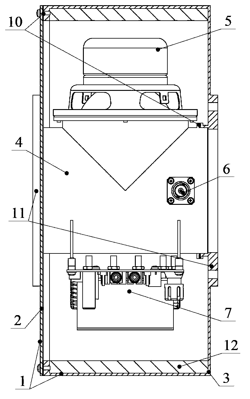
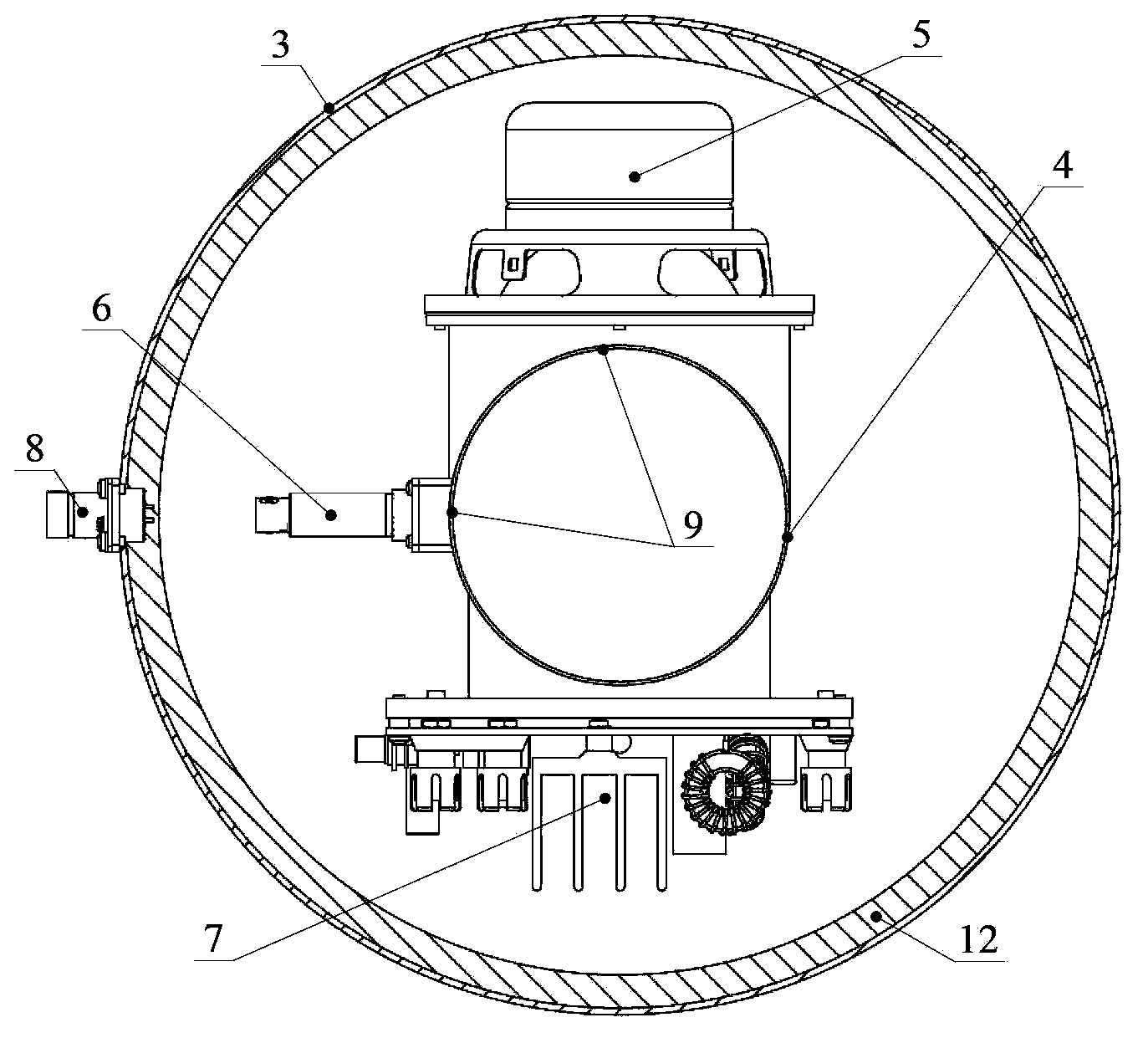
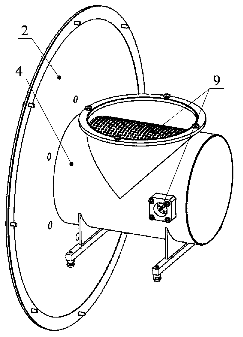
[0029] refer to figure 1 and figure 2 , the active muffler for the ventilation pipeline system provided by the present invention includes a shell 1, an inner pipe section 4, a speaker unit 5, an error microphone 6 and a speaker power amplifier board 7; wherein, the shell 1 includes a cover 2 and a shell body 3; the cover 2 is a plate-shaped structure with a hole in the center, the housing 3 is a barrel-shaped structure with a hole in the center of the bottom, and one end of the inner pipe section 4 passes through the hole in the center of the cover 2 And fixed on the cover 2, the other end of the inner pipe section 4 is embedded in the hole at the center of the housing 3, the cover 2 is installed on the top of the housing 3; the inner pipe section Around 4, described loudspeaker unit 5, error microphone 6 and loudspeaker power amplifier board 7 are installed respectively, whe


PUM

PropertyMeasurementUnit
Diameteraaaaaaaaaa

Abstract

The invention relates to an active sound eliminator for a ventilation pipeline system. The active sound eliminator comprises an outer shell, an inner pipe segment, a loudspeaker unit, an error microphone and a loudspeaker power amplifier board card. The outer shell comprises a sealing cover and a shell body, the sealing cover is of a plate-shaped structure with an opening in the center, the shell body is of a barrel-shaped structure with an opening in the bottom central position, one end of the inner pipe segment penetrates through the hole in the center of the sealing cover and is fixed to the sealing cover, the other end of the inner pipe segment is embedded in the hole in the center of the shell body, and the sealing cover is arranged on the top of the shell body. The loudspeaker unit, the error microphone and the loudspeaker power amplifier board card are respectively arranged on the periphery of the inner pipe segment, an output interface of the loudspeaker power amplifier board card is connected with the loudspeaker unit, and a signal input interface and a power source interface of the loudspeaker power amplifier board card and an output interface of the error microphone are led out through an electric connector arranged on the shell body. An annular flange for containing the loudspeaker unit is arranged on the side face of the inner pipe segment, and a plurality of penetrating holes exist in the position, corresponding to the mounting positions of the loudspeaker unit and the error microphone, of the wall of the inner pipe segment.

Description


Claims


Application Information

Patent Timeline
Owner IOASONIC SU ZHOU TECH CO LTD
Why Eureka
Try Eureka