Virtual IP realization method
A network card and application service technology, applied in electrical components, transmission systems, etc., can solve the problems of increasing network construction and maintenance costs, labor costs, etc., and achieve good scalability, save labor costs, and reduce construction and maintenance costs. Effect
- Summary
- Abstract
- Description
- Claims
- Application Information
AI Technical Summary
Problems solved by technology
Method used
Image


Examples
Example Embodiment
[0045] Example 1
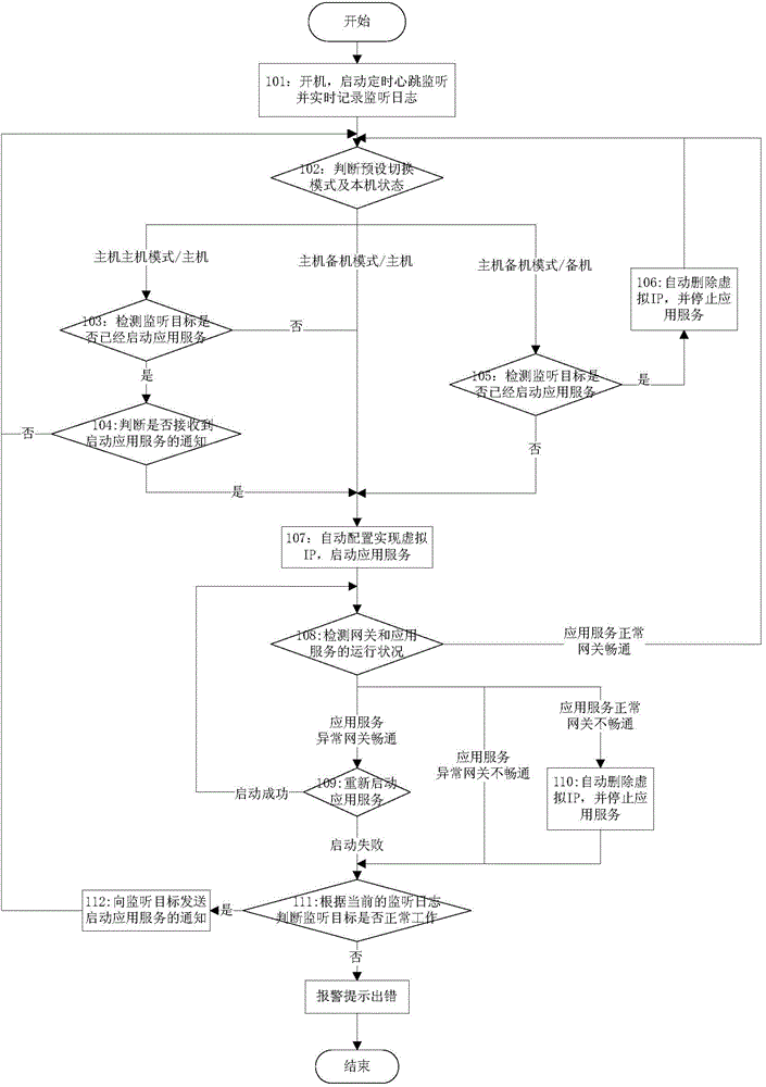
[0046] In order to have a deeper understanding of the implementation method of a virtual IP provided by the present invention, first, in Embodiment 1, the use of the implementation method of the virtual IP proposed by the present invention in the dual-system hot standby application scenario is described, as shown in figure 1 As shown, the details are as follows:
[0047] Step 101: start the machine, start the regular heartbeat monitoring and record the monitoring log in real time;
[0048] Step 102: Determine the preset switching mode and the state of the machine. If it is the master host mode / master, go to step 103; if it is the master backup mode / master, go to step 107; if it is the master backup mode / standby, go to step 105;
[0049] In this embodiment, preferably, the preset switching modes shown include host host mode, host standby mode, and host standby mode, and the state of the local machine can be host or standby.
[0050] Step 103: Detect whe
Example Embodiment
[0085] Example 2
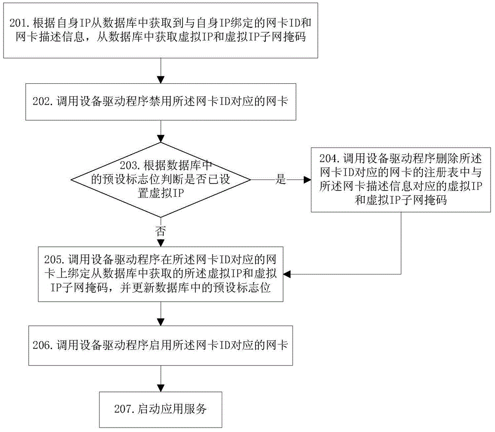
[0086] like image 3 Shown is a kind of virtual IP realization method based on Windows platform provided by this embodiment 2, including the following contents:
[0087] Step 301: Obtain the network card ID and network card description information bound to the IP from the database according to its own IP;
[0088] For example, its own IP is 192.168.16.47.
[0089] Step 302: Obtain the virtual IP and virtual IP subnet mask from the database;
[0090] For example: the virtual IP is 192.168.25.200, and the virtual IP subnet mask is 255.255.255.0.
[0091] Step 303: Obtain the field value indicating whether the virtual IP has been set from the database;
[0092] For example: the obtained field value is flag.
[0093] Step 304: Call the SetupDiGetClassDevs function to obtain the installed device information set;
[0094] For example: the obtained installed device information collection is:
[0095] ({650D5BB1-9BB4-45CD-90C8-ECE70B72EB35},
[0096] {E90A38FA-
Example Embodiment
[0134] Example 3
[0135] This embodiment is provided on the basis of the dual-system hot backup solution provided in Embodiment 1, wherein figure 1 The process of automatic configuration to realize virtual IP and start application service described in the specific implementation based on linux platform is as follows Pic 4-1 shown, including the following steps:
[0136] Step 401: Obtain the network card ID bound to its own IP from the database according to its own IP, and obtain the virtual IP and virtual IP subnet mask from the database;
[0137] For example, the obtained network card ID is eth0, the obtained virtual IP is 192.168.25.100, and the obtained virtual IP subnet mask is 255.255.255.0.
[0138] Step 402: Execute the query configuration information command;
[0139] For example: the query configuration information command is: ifconfig eth0:0.
[0140] Step 403: Judging whether the configuration information of the network card corresponding to the network card ID i
PUM
 Abstract
Description
Claims
Application Information
 - R&D Engineer
- R&D Manager
- IP Professional
- Industry Leading Data Capabilities
- Powerful AI technology
- Patent DNA Extraction
Browse by: Latest US Patents, China's latest patents, Technical Efficacy Thesaurus, Application Domain, Technology Topic.
© 2024 PatSnap. All rights reserved.Legal|Privacy policy|Modern Slavery Act Transparency Statement|Sitemap