Steel bar forming mechanical equipment for building
A technology for mechanical equipment and construction, applied in the field of steel bar forming machinery and equipment for construction, can solve the problems of inability to automatically feed and fix steel bars, and achieve the effects of reducing manual operations, preventing collapse, and being easy to use.
- Summary
- Abstract
- Description
- Claims
- Application Information
AI Technical Summary
Problems solved by technology
Method used
Image

Examples
Embodiment 1
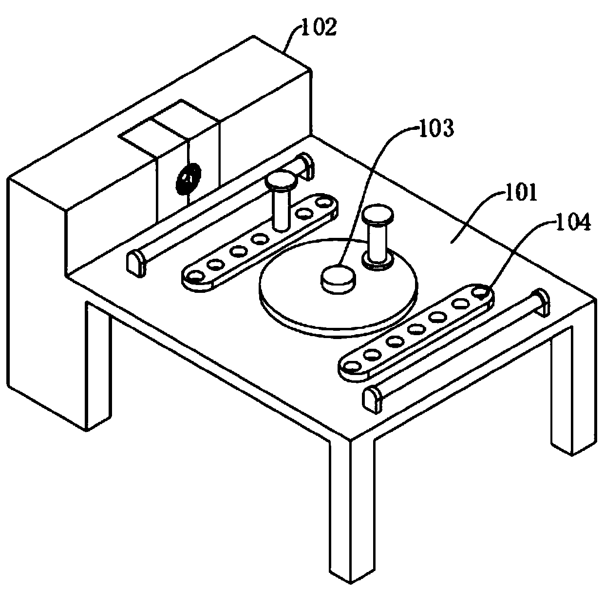
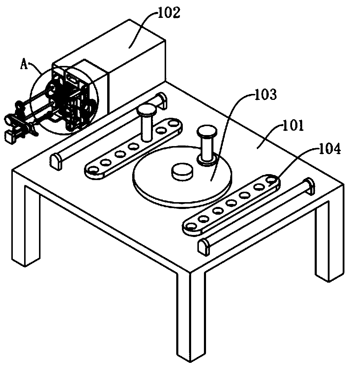
[0027] A mechanical equipment for forming steel bars for construction, comprising: a supporting main frame 101, a limiting main frame 102, and a steel bar bending turntable 103, the upper surface of the supporting main frame 101 is fixedly installed on the left side with a limiting main frame 102, and the upper surface of the supporting main frame 101 The steel bar bending turntable 103 is fixedly installed in the middle, and the upper surface of the supporting main frame 101 is located on the left and right sides of the steel bar bending turntable 103. The movable limit pillars 104 are fixedly installed, and the inner middle part of the limit main frame 102 is sequentially provided with feeding Storehouse 105 and fixed storehouse 106, limit main frame 102 inner side middle part front and rear sides all are provided with drive storehouse 107, drive storehouse 107 inside is provided with drive mechanism, and drive mechanism is meshed and connected with primary limit mechanism on ...
Embodiment 2
[0029] Embodiment 2: Based on Embodiment 1, the difference is:
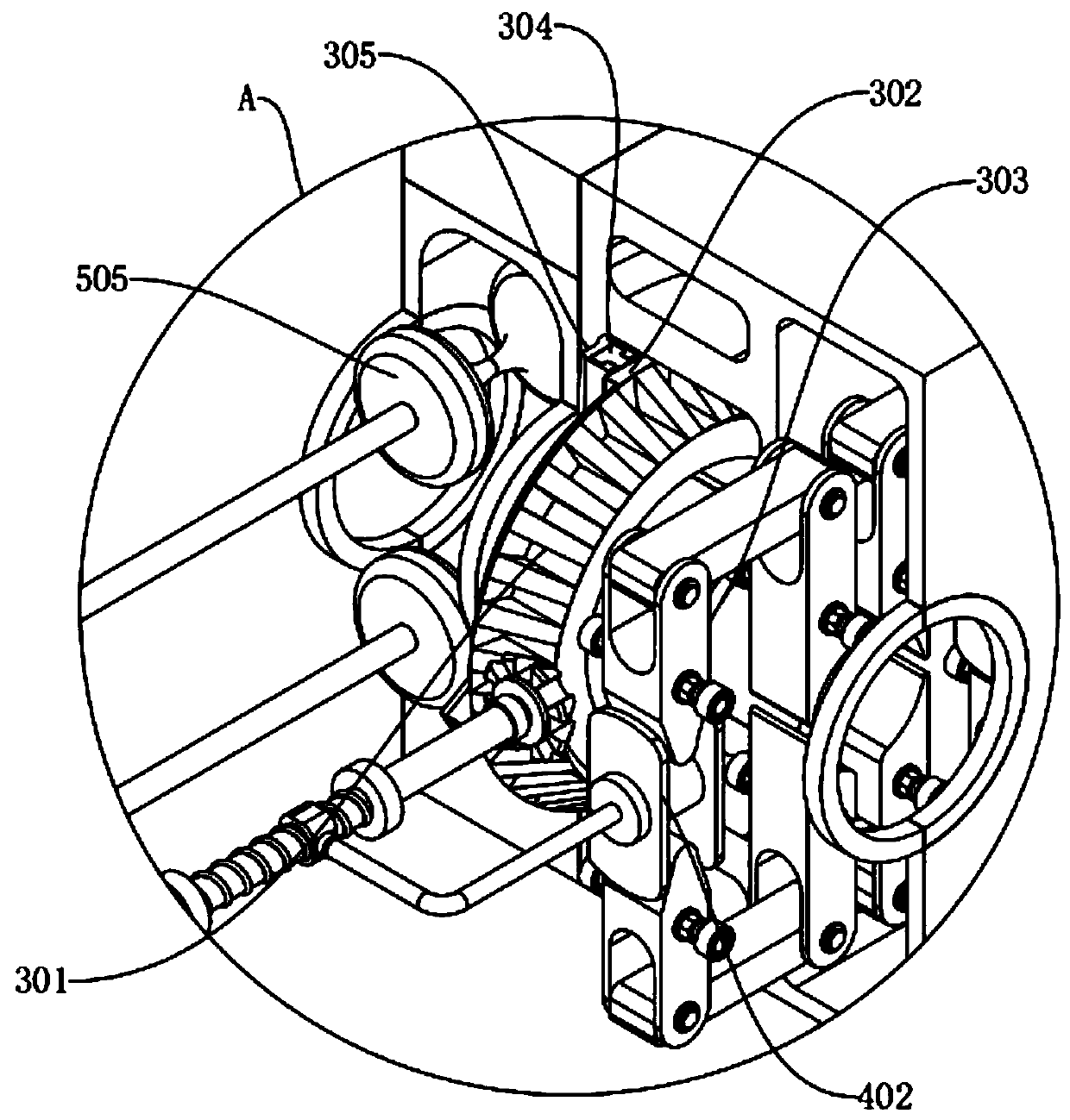
[0030] The driving mechanism includes: a servo motor 201, a rotating wheel set 202, a rotating screw mandrel 203, a moving block 204, a moving rod 205 and a limit gear 206, and a servo motor 201 is fixedly installed on the outer side of the driving chamber 107, and the servo motor 201 is a main shaft. The front end is fixedly connected with the rotating wheel set 202, the rotating screw mandrel 203 and the limit gear 206 sequentially from the outside to the inside, the moving block 204 is threaded on the rotating screw mandrel 203, and the right side of the moving block 204 is fixed to the outer end of the moving rod 205 Connected, the inner end of the moving rod 205 is fixedly connected with the secondary limit mechanism, the limit gear 206 is meshed with the primary limit mechanism, and the left side of the rotating wheel set 202 is fixedly connected with the feeding mechanism.
[0031] The primary limiting mec...
Embodiment 3
[0035] Embodiment 3: Based on Embodiment 1 and 2, but the difference is:
[0036] The feeding mechanism includes: a rotating shaft 501, a rotating gear 502, a transmission gear 503, a transmission shaft 504, and a feeding roller 505. The inner wall of the warehouse 107 is fixedly connected, the other end of the rotating shaft 501 is fixedly connected to the axis center of the rotating gear 502, the upper and lower sides of the rotating gear 502 are meshed with the transmission gear 503, and the axis center of the transmission gear 503 is fixedly connected to the outer end of the transmission shaft 504. The inner end of 504 runs through the drive chamber 107 and extends to the feed chamber 105, and is fixedly connected with the axis of the front and rear sides of the feed roller 505.
[0037] The present invention is provided with a feeding mechanism, by starting the reverse rotation of the servo motor 201 to drive the rotating wheel set 202 to rotate, driving the rotating shaf...
PUM
 Abstract
Description
Claims
Application Information
 - R&D Engineer
- R&D Manager
- IP Professional
- Industry Leading Data Capabilities
- Powerful AI technology
- Patent DNA Extraction
Browse by: Latest US Patents, China's latest patents, Technical Efficacy Thesaurus, Application Domain, Technology Topic.
© 2024 PatSnap. All rights reserved.Legal|Privacy policy|Modern Slavery Act Transparency Statement|Sitemap