Automatic reversing edge trimmer

An automatic reversing and trimming machine technology, applied in metal processing and other directions, can solve the problems of increasing the complexity of the trimming machine structure and increasing the manufacturing cost of the trimming machine, so as to simplify the structure of the trimming machine, reduce production costs, reduce The effect of the number of driving parts

Active Publication Date: 2015-03-04
SUZHOU SHENGCHENG SOLAR EQUIP
View PDF7 Cites 5 Cited by
  • Summary
  • Abstract
  • Description
  • Claims
  • Application Information

AI Technical Summary

Problems solved by technology

[0002] In the production process of solar panels, there will be large and small burrs on the four sides of the solar panel, so the burrs need to be trimmed. The current trimming machine needs four cutter heads to trim the f

Method used


Image

  • Automatic reversing edge trimmer
  • Automatic reversing edge trimmer

Examples


Embodiment Construction

[0011] Below in conjunction with the embodiment shown in the accompanying drawings, the present invention is described in detail as follows:

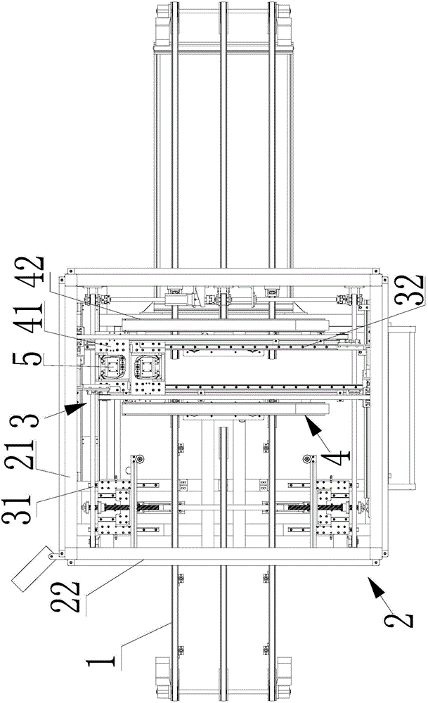
[0012] Such as figure 1 As shown, the automatic reversing trimming machine includes a conveying frame 1, a frame 2 covered on the conveying frame 1, a longitudinal driving part 3 connected to the frame 2 and moving along the conveying direction of the conveying frame 1, installed in the longitudinal The horizontal driving part 4 that can move along the conveying direction perpendicular to the longitudinal driving part 3 on the driving part 3, the vertical driving part 5 that is installed below the horizontal driving part 4 and can move along the direction perpendicular to the upper end surface of the conveying frame 1 , The cutter head installed on the vertical drive part 5.

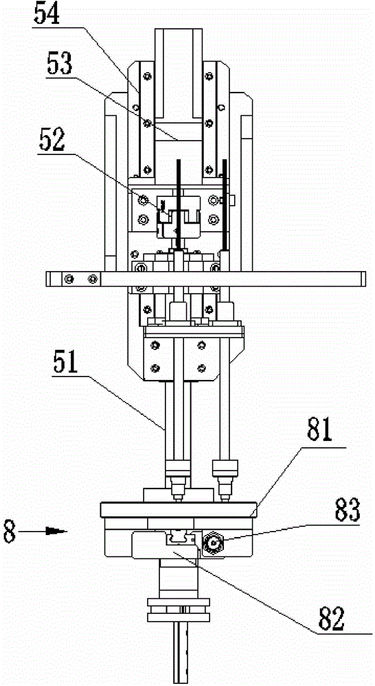
[0013] The vertical driving part 5 includes a buffer device 8 connected to the cutter head, a connecting rod 51 connected to the buffer device 7, a motor 53 connect


PUM


Abstract

The invention discloses an automatic reversing edge trimmer which comprises a conveying frame, a framework, a longitudinal driving portion, a transverse driving portion, a vertical driving portion and a cutter bit. The framework covers the conveying frame, the longitudinal driving portion is connected onto the framework and can move along the conveying direction of the conveying frame, the transverse driving portion is mounted on the longitudinal driving portion and can move along the direction perpendicular to the conveying direction of the longitudinal driving portion, the vertical driving portion is mounted below the transverse driving portion and can move along the direction perpendicular to the upper end surface of the conveying frame, and the cutter bit is mounted on the vertical driving portion. The automatic reversing edge trimmer has the advantages that the cutter bit can move back and forth, left and right and up and down under the control of the longitudinal driving portion, the transverse driving portion and the vertical driving portion, so that the peripheries of solar panels can be trimmed by the automatic reversing edge trimmer, the quantities of cutter bits and driving components for driving the cutter bits to move can be reduced, the structure of the edge trimmer can be simplified, and the production cost can be reduced.

Description


Claims


Application Information

Patent Timeline
Owner SUZHOU SHENGCHENG SOLAR EQUIP
Why Eureka
Try Eureka