Cutter head molding machine

A technology of molding machine and cutter head, applied in the direction of manufacturing tools, grinding racks, grinding machine parts, etc., can solve problems such as low production efficiency, and achieve the effect of improving processing efficiency, improving molding accuracy and ensuring stability

Pending Publication Date: 2022-07-22
SHANGHAI WELL SUN PRECISION TOOLS
View PDF0 Cites 0 Cited by
  • Summary
  • Abstract
  • Description
  • Claims
  • Application Information

AI Technical Summary

Benefits of technology

This patented technology allows for precise movement of an abrasive tool used with a milling machine without having to manually move it around or reposition itself when changing tracks. It simplifies the overall operation and increases productivity while maintaining stable performance over longer periods of use.

Problems solved by technology

This patented technical problem addressed in this patents relates to improving the manufacturing efficiency of rotating tools that use high-quality metals like steel or cerium instead of traditional methods such as carbide cutting tools.

Method used


Image

  • Cutter head molding machine
  • Cutter head molding machine
  • Cutter head molding machine

Examples


Embodiment Construction

[0034] Attached to the following Figure 1-4 This application will be described in further detail.

[0035] The embodiment of the present application discloses a cutter head molding machine.

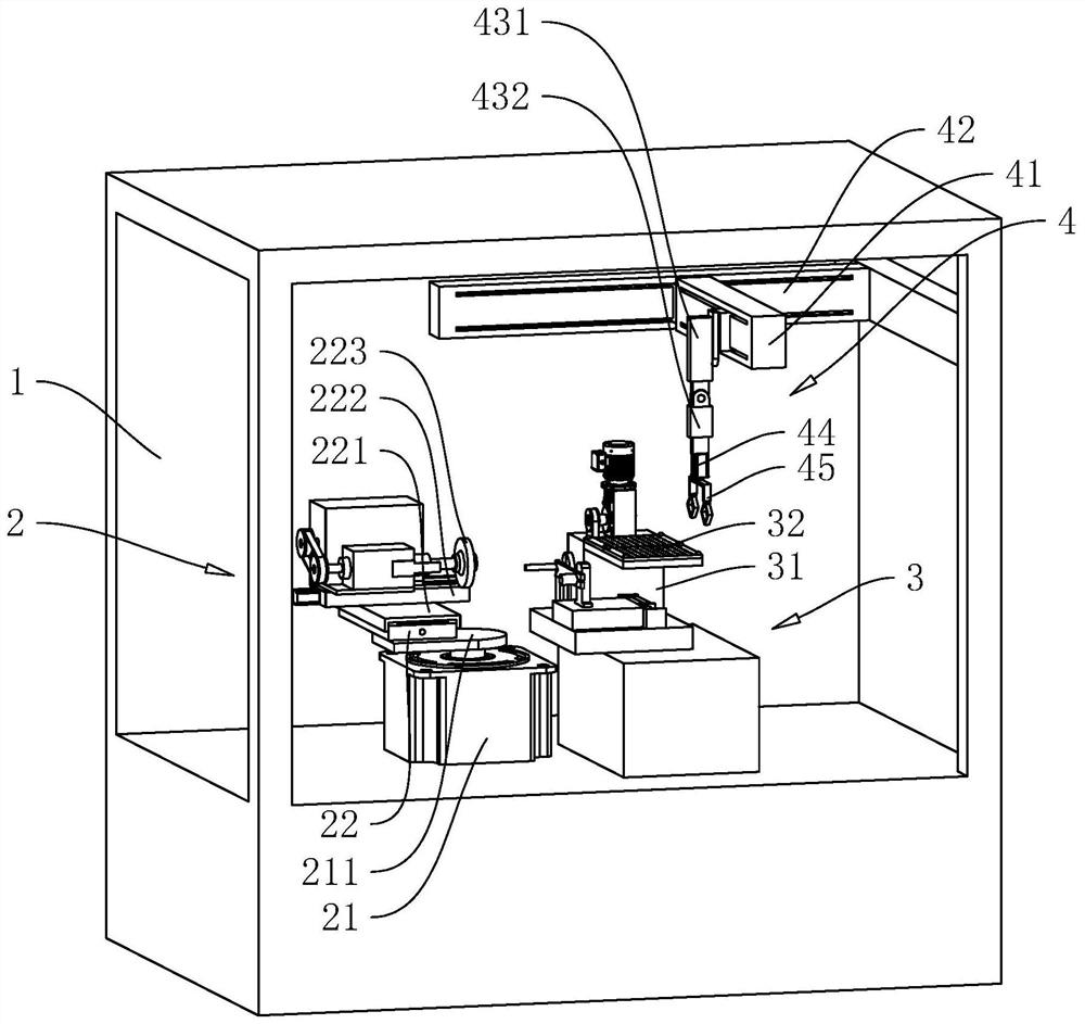
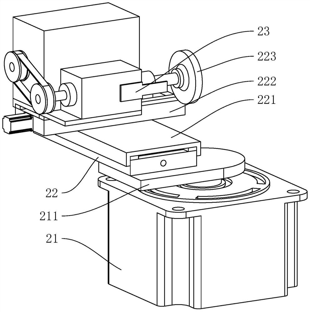
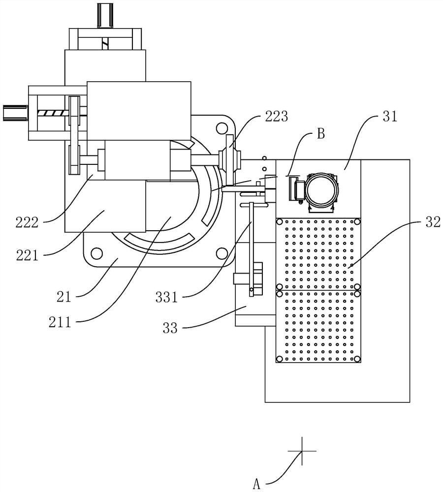
[0036] refer to figure 1 and figure 2 , a cutter head molding machine includes a frame 1, the frame 1 is provided with a modeling assembly 2, a fixing assembly 3 and a feeding assembly 4, and the modeling assembly 2 includes a rotating motor 21 fixed on the base of the frame 1, which rotates A turntable 211 is fixedly connected to the output shaft of the motor 21 , a fixing block 22 is fixedly arranged on the turntable 211 , a first sliding block 221 is arranged on the fixing block 22 through the sliding of a screw rod, and the first sliding block 221 is provided with a screw rod. The sliding is provided with a second sliding block 222, the sliding direction of the first sliding block 221 and the sliding direction of the second sliding block 222 are perpendicular to each other; the seco


PUM


Abstract

The invention discloses a cutter head molding machine, and relates to the field of cutter machining, the cutter head molding machine comprises a rack, the rack is provided with a fixing assembly used for fixing a to-be-machined cutter head, a feeding assembly used for conveying the to-be-machined cutter head to the fixing assembly and taking the machined cutter head, and a molding assembly used for polishing the to-be-machined cutter head; the modeling assembly comprises a rotating motor fixedly arranged on the rack base, the rotating motor is coaxially connected with a rotating table, the rotating table is rotationally connected with a grinding wheel, and the grinding wheel is adjustably arranged on the rotating table in a sliding mode in the horizontal direction; by means of rotation of the rotary table and horizontal movement of the polishing grinding wheel on the rotary table, the track machining face of the tool bit to be machined can be formed at a time through the polishing grinding wheel, and the beneficial effects that the forming precision is high, the machining precision is high, and the machining precision is high are achieved. And the processing efficiency is high.

Description


Claims


Application Information

Patent Timeline
Owner SHANGHAI WELL SUN PRECISION TOOLS
Why Eureka
Try Eureka