Micro-fluidic chip for preparing microspheres and using method of micro-fluidic chip
A microfluidic chip and chip technology, applied in the direction of microsphere preparation, chemical instruments and methods, microcapsule preparations, etc., can solve the problems of increased production cost, use cost, lack of microfluidic chips, difficulty in popularization and use, etc. , to achieve the effect of low cost of use, small particle size dispersion and strong professionalism
- Summary
- Abstract
- Description
- Claims
- Application Information
AI Technical Summary
Benefits of technology
Problems solved by technology
Method used
Image

Examples
Embodiment 1
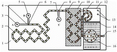
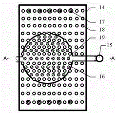
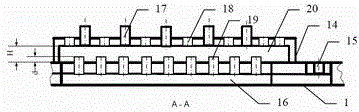
[0023] refer to Figure 1 to Figure 5 The shape structure in , a microfluidic chip for preparing microspheres, has an injection hole A3, an injection hole B5 and an injection hole C7. The V-shaped opening angle of the V-shaped mixing pipe is 30°, and the side length is 3mm. All channels on the chip are 500 μm wide and 300 μm deep. The height of the cold water storage cavity 22 of the cooling chip 12 is 3mm; the thickness T=3mm above the cooling double U-shaped pipe 11, and the depth of the cooling pit 21 is t=2mm. On the surface of the volatilization exhaust chip 14, five air pipes 17 are processed and installed on both sides of the rectangle, and 100 volatilization exhaust holes 18 are processed side by side on the other surfaces; the height of the exhaust cavity 20 of the volatilization exhaust chip 14 is H=3mm , the height d of the exhaust pipe 19 of the shaped collection pool protruding from the surface of the chip body 1 = 1.5 mm.
[0024] During operation, prepare 1% pol
Embodiment 2
[0028] refer to Figure 1 to Figure 5 The shape structure in , a microfluidic chip for preparing microspheres, the V-shaped opening angle of the V-shaped mixing channel is 60°, and the side length is 5mm. All channels on the chip are 100 μm wide and 100 μm deep. The height of the cold water storage cavity 22 of the cooling chip 12 is 2 mm; the thickness T=2 mm above the cooling double U-shaped pipe 11, and the depth of the cooling pit 21 is t=1 mm. On the surface of the volatilization exhaust chip 14, 10 ventilation pipes 17 are processed and installed on both sides of the rectangle, and 50 volatilization exhaust holes 18 are processed side by side on the other surfaces; the height of the exhaust cavity 20 of the volatilization exhaust chip 14 is H=2mm , the height of the exhaust pipe 19 of the shaped collection pool protruding from the surface of the chip body 1 is d = 1 mm.
[0029] The operation method is according to the first embodiment, and the round microspheres are obtain
Embodiment 3
[0031] refer to Figure 2 to Figure 6 The shape structure in , a microfluidic chip for preparing microspheres, has an injection hole A 3 , an injection hole B 5 , an injection hole D and an injection hole C 7 . The V-shaped opening angle of the V-shaped mixing pipe is 45°, and the side length is 4mm. All channels on the chip are 80 μm wide and 50 μm deep. The height of the cold water storage cavity 22 of the cooling chip 12 is 4 mm; the thickness T above the cooling double U-shaped pipe 11 is 4 mm, and the depth of the cooling pit 21 is t = 3 mm. On the surface of the volatilization exhaust chip 14, eight air pipes 17 are processed and installed on both sides of the rectangle, and 25 volatilization exhaust holes 18 are processed side by side on the other surfaces; the height of the exhaust cavity 20 of the volatilization exhaust chip 14 is H=4mm , the height of the exhaust pipe 19 of the shaped collection pool protruding from the surface of the chip body 1 is d = 2 mm.
[0032
PUM
| Property | Measurement | Unit |
|---|---|---|
| Opening angle | aaaaa | aaaaa |
| Particle size | aaaaa | aaaaa |
Abstract
Description
Claims
Application Information
 - R&D Engineer
- R&D Manager
- IP Professional
- Industry Leading Data Capabilities
- Powerful AI technology
- Patent DNA Extraction
Browse by: Latest US Patents, China's latest patents, Technical Efficacy Thesaurus, Application Domain, Technology Topic.
© 2024 PatSnap. All rights reserved.Legal|Privacy policy|Modern Slavery Act Transparency Statement|Sitemap