Novel integral gear shift handle mechanism

A shift handle, an integrated technology, applied in the direction of mechanical equipment, engine components, transmission device control, etc., can solve the problems of easy looseness at the interface, inconvenient use, and remote shift handles, etc., to achieve outstanding substantive features and increase Overall strength, strong and reliable connection

Inactive Publication Date: 2015-05-13
SINO TRUK JINAN POWER
View PDF0 Cites 1 Cited by
  • Summary
  • Abstract
  • Description
  • Claims
  • Application Information

AI Technical Summary

Problems solved by technology

[0002] The transmission on a heavy-duty vehicle needs a manipulation control device to switch between high and low gears; The device is installed on the shift handle, and the driver can realize the purpose of switching between the high and low gears of the transmission through the joystick, which is very convenient to use
[0003] The existing shift handle that can switch high and low gears is convenient for the driver to control the switching between high and low gears, but after a long period of use, it is found that there are the following shortcomings: On the one hand, in this scheme, the joint seat and the valve body are Two separate structures, the joint seat is set at the lower part of the valve body, and the joint is located in the joint seat. Because the contact area between the bottom surface of the valve body and the shift rod nut is small, the valve body will be broken after long-term use; the other On the one hand, what is used in the prior art is a rubber joint. The lower part of the joint is connected to the air pipe of the transmission. Due to the need for frequent shifts, the joint between the joint and the air pipe is easy to loosen, and sometimes air leakage accidents may occur.

Method used


Image

  • Novel integral gear shift handle mechanism
  • Novel integral gear shift handle mechanism

Examples


Embodiment Construction

[0014] In order to clearly illustrate the technical features of the solution, the solution will be described below through a specific implementation mode combined with the accompanying drawings.

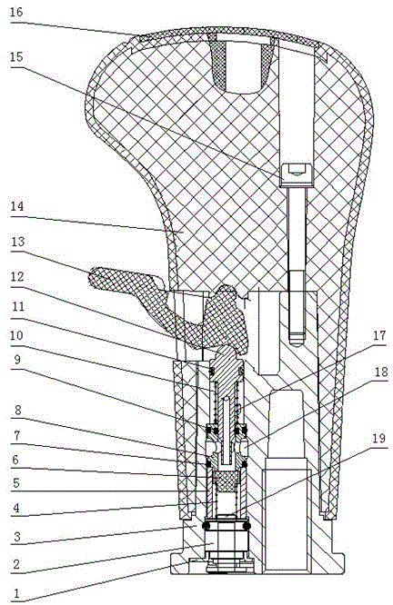
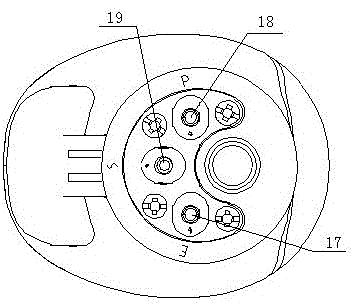
[0015] It can be seen from the accompanying drawings that a new type of integrated shift handle mechanism includes a shift handle for adjusting different gear positions, and the shift handle is provided with a switching valve for realizing high and low gear conversion of the transmission. The switching valve includes a valve body 3 and a valve core 12, and the valve body 3 is fixed on the handle valve casing 14 through a hexagon socket head screw 15; the valve core 12 is provided with a sealing ring III11, and the valve body 3 and the valve core Between 12, there is also a valve sleeve 8 which plays a sealing role. The valve sleeve 8 is provided with a sealing ring II9. The valve sleeve 8 cooperates with the sealing ring to realize the sealing of the valve core 12. The spool 12 is co...


PUM


Abstract

The invention provides a novel integral gear shift handle mechanism. The novel integral gear shift handle mechanism comprises a gear shift handle and a switching valve, wherein a handle valve gear adjusting button for controlling the state of the switching valve is arranged at the upper part of a valve core of the switching valve; a guide sleeve acting a guide effect is arranged at the lower part of the valve core; a rubber plug is arranged in the guide sleeve; and a joint is arranged at the lower part of the guide sleeve. The novel integral gear shift handle mechanism is characterized in that a valve body and a joint base for fixing the joint are formed to an integrated structure; the joint is fixed at the lower part in the valve body, and is connected with the rubber plug by a rubber plug spring; and an air source inlet, a control output port and an exhaust port are arranged on the joint. The joint base and the valve body are formed to an integrated cast aluminum structure, so that the contact area of the bottom surface of the valve body and a control rod nut is increased, and the generation of rupture phenomenon of the valve body is prevented; and the joint is fixed at the lower part in the valve body, adopts a metal material, and is firm and reliable in connection with an air pipe, so that the air leaking phenomenon of a handle valve is effectively solved.

Description

technical field [0001] The invention relates to an automobile handle mechanism, in particular to a novel integral shift handle mechanism. Background technique [0002] The transmission on a heavy-duty vehicle needs a manipulation control device to switch between high and low gears; The device is installed on the shift handle, and the driver can realize the purpose of switching the high and low gear areas of the transmission through the joystick, which is very convenient to use. [0003] The existing shift handle that can switch high and low gears is convenient for the driver to control the switching between high and low gears, but after a long period of use, it is found that there are the following shortcomings: On the one hand, in this scheme, the joint seat and the valve body are Two separate structures, the joint seat is set at the lower part of the valve body, and the joint is located in the joint seat. Because the contact area between the bottom surface of the valve bo...

Claims


Application Information

Patent Timeline
IPC IPC(8): F16H59/10F16K1/00
CPCF16H59/10
Inventor 马书会赵波连水梅李法友刘鑫刘森刘振
Owner SINO TRUK JINAN POWER
Why Eureka
Try Eureka