Disperse relaxation factor tidal current model based minimum electricity generating cost incremental quantity obtaining method

A relaxation factor, power flow model technology, used in data processing applications, instrumentation, forecasting, etc.

Inactive Publication Date: 2015-05-13
HOHAI UNIV
View PDF3 Cites 6 Cited by
  • Summary
  • Abstract
  • Description
  • Claims
  • Application Information

AI Technical Summary

Problems solved by technology

Therefore, there is no method in the prior art that can effectively and quickly obtain the system λ and control the system λ

Method used


Image

  • Disperse relaxation factor tidal current model based minimum electricity generating cost incremental quantity obtaining method
  • Disperse relaxation factor tidal current model based minimum electricity generating cost incremental quantity obtaining method
  • Disperse relaxation factor tidal current model based minimum electricity generating cost incremental quantity obtaining method

Examples


Embodiment

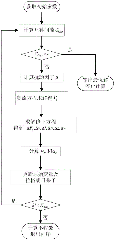
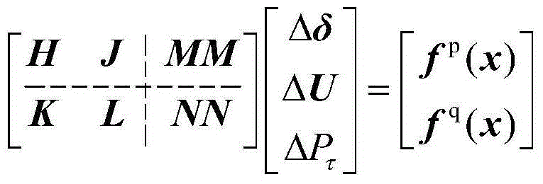
[0037] Step 1: Establish a power flow calculation model for decentralized relaxation factors:

[0038]

[0039] In the formula, x=[P τ ,U,δ], Δδ, ΔU, ΔP τ Respectively, the voltage phase angle, the voltage amplitude, and the correction value f of the active power unbalance p (x) is active residual, f q (x) is reactive residual:

[0040] f i p ( δ , U , P τ ) = P gi 0 - P li - P ei ( δ , U ) + α i P τ

[0041] f i q ...


PUM


Abstract

The invention discloses a disperse relaxation factor tidal current model based minimum electricity generating cost incremental quantity obtaining method. When a minimum electricity generating cost incremental quantity model only containing one balance node tidal current model is solved, the total demand unit change of a system is fixed on a balance node, and an obtained lambda, namely electricity generating cost minimum incremental quantity cannot reflect actual operation of the system in most cases during total demand unit change of a system. The disperse relaxation factor tidal current model based minimum electricity generating cost incremental quantity obtaining method adopts solves the provided model by means of an original antithesis interior point method, and the lambda of the system is controllable according to selected disperse relaxing factors.

Description

technical field [0001] The invention belongs to the technical field of power system operation and control, and in particular relates to a method for acquiring minimum power generation cost increments based on a decentralized relaxation factor power flow model. Background technique [0002] For each power system, when the total load of the system changes per unit (that is, the unit change will be distributed to each node of the system according to the distributed relaxation factor), the active power of the generator will have an optimal unit increment, and λ is the optimal unit The minimum power generation cost increment corresponding to the increment. [0003] The size of the general system λ depends on the power flow model used, so when solving the economic dispatch of the traditional power flow model, the obtained system λ is the minimum increment of the generator cost when the total demand unit change of the system is fixed at the balance node. In particular, if two inte...

Claims


Application Information

Patent Timeline
IPC IPC(8): G06Q10/04G06Q50/06
CPCG06Q10/04G06Q50/06Y02E40/70Y04S10/50
Inventor 卫志农黄为民孙国强孙永辉向育鹏
Owner HOHAI UNIV
Why Eureka
Try Eureka