Program generating apparatus and program generating method
- Summary
- Abstract
- Description
- Claims
- Application Information
AI Technical Summary
Benefits of technology
Problems solved by technology
Method used
Image

Examples
first embodiment
[Configuration of Program Generating Apparatus]
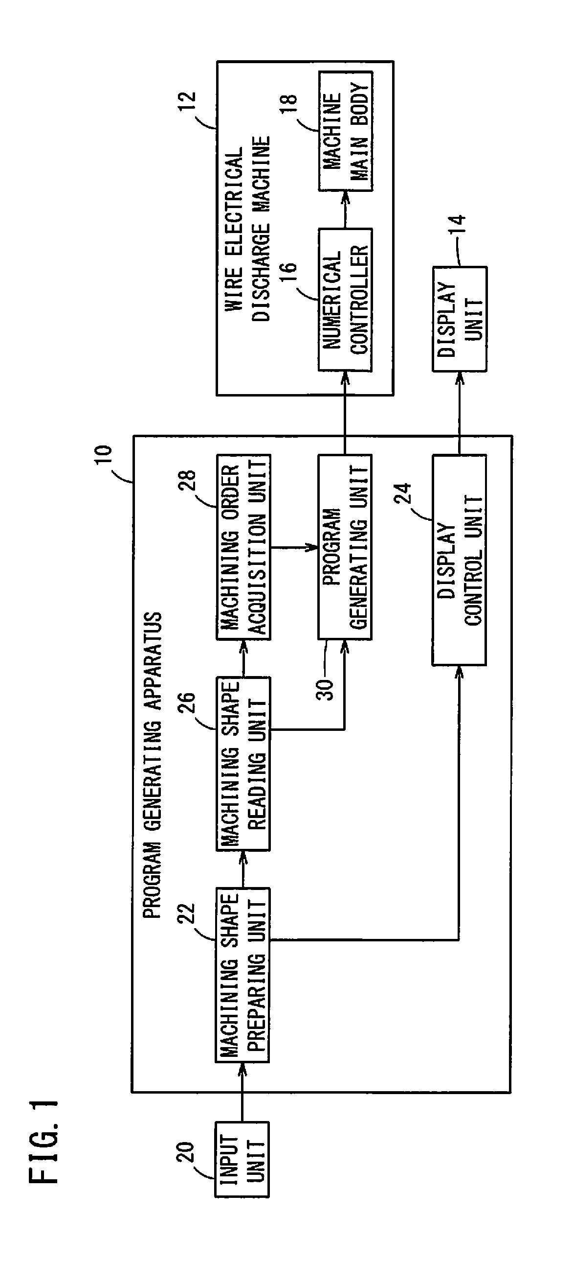
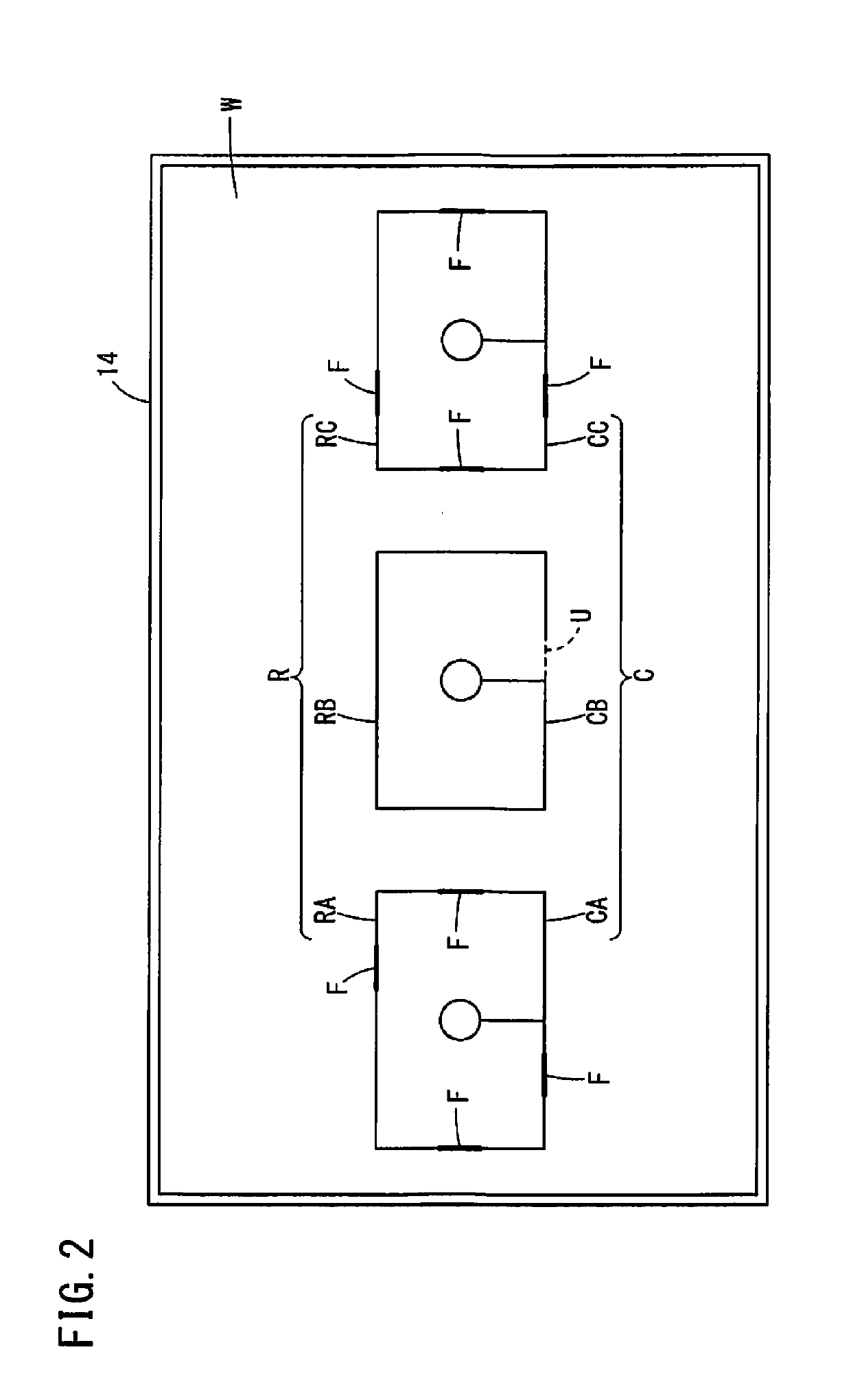
[0015]FIG. 1 is a block diagram showing a program generating apparatus 10 and a wire electrical discharge machine 12. FIG. 2 is a diagram showing an example of machining paths R and cores C in a workpiece W displayed on a display unit 14. In the example of FIG. 2, the workpiece W has machining paths RA, RB and RC for defining a machining shape. When rough machining is performed on the workpiece W, cores CA, CB and CC are produced.
[0016]Hereinbelow, as shown in FIG. 2, a machining path R indicates a single continuous line on a plane of the workpiece W, and a route drawn by such a single continuous line is counted as one machining path R. Therefore, the workpiece W shown in FIG. 2 contains three machining paths RA, RB, RC. In the following description, the person who performs operation or the like of the program generating apparatus 10 is referred to as a user, while the person who performs operation or the like of the wire electrical discha
second embodiment
[0043]FIG. 4 is a block diagram showing a program generating apparatus 32, a program generating apparatus 10, and a wire electrical discharge machine 12.
[0044]The program generating apparatus32 is, for example, a personal computer or the like equipped with CAD / CAM software. The program generating apparatus 32 generates an NC program for controlling the wire electrical discharge machine 12 according to machining paths R on the workpiece W, which are input by the user.
[0045]The program generating apparatus 10 is a personal computer or the like equipped with CAD / CAM software. The program generating apparatus 10 reads an NC program generated by the program generating apparatus 32, and modifies the NC program. The program generating apparatus 32 and the program generating apparatus 10 may be personal computers or the like on which the same application is installed. For example, the program generating apparatus 32 may be used in an office by a user in charge of programming while the prog
PUM
 Abstract
Description
Claims
Application Information
 - R&D Engineer
- R&D Manager
- IP Professional
- Industry Leading Data Capabilities
- Powerful AI technology
- Patent DNA Extraction
Browse by: Latest US Patents, China's latest patents, Technical Efficacy Thesaurus, Application Domain, Technology Topic.
© 2024 PatSnap. All rights reserved.Legal|Privacy policy|Modern Slavery Act Transparency Statement|Sitemap