Combined type plane building template structure
A technology of building formwork and planar formwork, which is applied in the direction of building structure, formwork/formwork components, construction, etc., can solve the problems of increasing construction costs, increasing production costs of enterprises, and low construction efficiency, so as to facilitate construction and handling, improve Number of turnovers and the effect of improving construction efficiency
- Summary
- Abstract
- Description
- Claims
- Application Information
AI Technical Summary
Benefits of technology
Problems solved by technology
Method used
Image


Examples
Embodiment 1
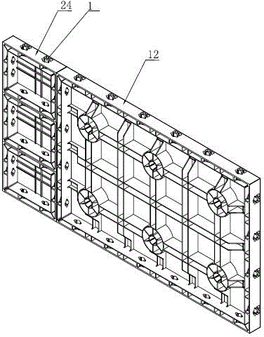
[0036] When the spliced size of multiple planar templates 12 cannot meet the needs of wall construction, such as figure 1 As shown, first pass the handle ( figure 1 not shown in ) to splice a plurality of interlocking templates 24 along the longitudinal direction to form an interlocking template assembly, and then pass the combined interlocking template assembly through the handle ( figure 1 (not shown in ) is connected with the plane formwork 12, so as to form a wall formwork that meets the construction requirements. figure 1 (not shown in ), and then pour concrete between the two wall formworks. After the concrete is solidified, remove the handle and end face fixing plate, and remove the outer wall formwork and inner wall formwork respectively. After removal, the concrete wall will be exposed. Just cut off the pull bolts. The interlocking formwork 24 can also be connected to the planar formwork 12 along the horizontal splicing, and the vertical or horizontal splicing m
Embodiment 2
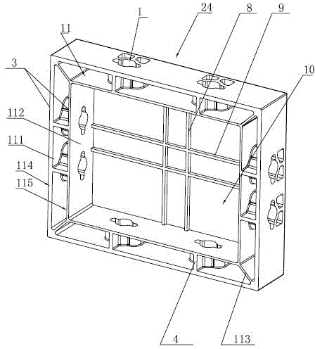
[0039] Such as Figure 5 As shown, each adjacent planar formwork 12 is fixedly connected through the handle (not shown in the figure) and the handle connection hole 1. One end of the handle has a flange matching the handle connection hole 1, and the other end of the handle is usually Handle-shaped, after extending the end of the handle with the flange into the connecting hole, the splicing of two adjacent planar templates 12 can be realized by rotating the handle-shaped end, and the outer side wall is formed by splicing a plurality of planar formworks 12 formwork, and then splicing a plurality of planar formworks 12 on the other side to form the inner side wall formwork, since the joints between the transverse reinforcement ribs 8, the longitudinal reinforcement ribs 9 and the inner wall of the frame 11 are all inclined downward and extend along the horizontal direction The low-position reinforcing rib 7 is formed, and the low-position reinforcing rib 7 prevents the handle from b
Embodiment 3
[0041] When it comes to walls of high height, such as Figure 6 As shown, at first two planar formworks 12 are docked, and the outer plates 111 of each planar formwork 12 are in contact with each other, and then the corner formwork 13 is inserted between the two planar formworks 12, and the corner formwork 13 is a hollow square steel material. There are a plurality of handle connection holes 1 on the corner formwork 13, and the handle connection holes 1 on the corner formwork 13 correspond to the handle connection holes 1 on each plane formwork 12. During the insertion process of the corner formwork 13 , two adjacent end surfaces of the corner formwork 13 are always attached to the side surfaces of the two plane formworks 12 . Then if Figure 5 As shown, a plurality of handles 14 are respectively inserted into the handle connection holes 1 of the plane formwork 12 and the corner formwork 13 to form a corner formwork system. In the actual operation process, the length of the corn
PUM
 Abstract
Description
Claims
Application Information
 - R&D Engineer
- R&D Manager
- IP Professional
- Industry Leading Data Capabilities
- Powerful AI technology
- Patent DNA Extraction
Browse by: Latest US Patents, China's latest patents, Technical Efficacy Thesaurus, Application Domain, Technology Topic.
© 2024 PatSnap. All rights reserved.Legal|Privacy policy|Modern Slavery Act Transparency Statement|Sitemap