Magnetic separator

A technology of magnetic separator and separation body, applied in the direction of magnetic separation, solid separation, chemical instruments and methods, etc. It can solve the problems of magnet load, affecting the adsorption efficiency of impurities such as iron filings, and the separation efficiency of the separator is not high, so as to meet the requirements of the work. Demand, the effect of high magnetic suction efficiency

Inactive Publication Date: 2015-08-12
台州飞亚鸿丰科技有限公司
View PDF9 Cites 2 Cited by
  • Summary
  • Abstract
  • Description
  • Claims
  • Application Information

AI Technical Summary

Problems solved by technology

[0004] The separation body on this separator has only one layer of separation surface on the upper surface for contacting with the liquid, which will affect the adsorption efficiency of the separator to iron filings and other impurities, and is not suitable for large liquid separation sites. The separation eff

Method used


Image

  • Magnetic separator
  • Magnetic separator

Examples


Embodiment Construction

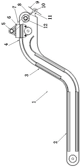
[0019] As shown in the figure, the magnetic separator of the present invention is the main structural part of the separator. The separator 1 is a hollow shell-shaped body, which is in the shape of a "Z" as a whole. The separator 1 has a liquid immersion part 2, a rising part 3 and a discharge Part 4, the immersion part 2 and the discharge part 4 are parallel, the rising part 3 is arranged obliquely and connects the immersion part 2 and the discharge part 4, and the discharge position of the separated material is located at the outer end of the discharge part 4 The outer end is also called the discharge end.

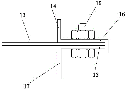
[0020] Separator 1 is surrounded by two side plates 17 and a closed annular flat plate 13. The separation surface on the separation body 1 is formed on the surface of flat plate 13. The separation surface is adapted to the direction of flat plate 13 and is also annular closed. The periphery of side plate 17 and flat plate 13 can be fixed together by the mode of welding, also


PUM


Abstract

The present invention discloses a magnetic separator, wherein the problem that the existing magnetic separator provides the relatively low adsorption efficiency for iron scraps in a liquid medium is solved with the magnetic separator of the present invention. The technical scheme comprises that the main body structure of the magnetic separator is a separated body, the separated body is provided with a power mechanism, a drive belt is arranged in the separated body, forms a transmission connection with the power mechanism, and is provided with a plurality of magnets, and the magnets are arranged at intervals along the length direction of the drive belt. The magnetic separator is characterized in that the separated body presents a Z shape and is provided with an infusion part, a rising part and a material discharge part, the three parts are smoothly connected into the integration, the rising part is positioned between the infusion part and the material discharge part, a separated surface is formed on the separated body surface and is an annular closed surface, the outer end portion of the material discharge part is the material discharge end, and a scraping device is arranged on the outer side of the separated body material discharge end and is used for scraping off the adsorbed substance on the separated surface along the material discharge direction.

Description


Claims


Application Information

Patent Timeline
Owner 台州飞亚鸿丰科技有限公司
Why Eureka
Try Eureka