Spatial filtering device

A technology of spatial filtering and filtering small holes, which is applied in the direction of optical components, optics, instruments, etc., can solve the problems of increasing the difficulty of small hole processing, alignment accuracy, sparking, etc., to increase misalignment tolerance, improve safety performance, Improve the effect of filtering effect

Active Publication Date: 2015-08-19
TECHNICAL INST OF PHYSICS & CHEMISTRY - CHINESE ACAD OF SCI
View PDF4 Cites 0 Cited by
  • Summary
  • Abstract
  • Description
  • Claims
  • Application Information

AI Technical Summary

Benefits of technology

This patented technology describes an improved space filter that uses multiple filters with different sizes for effective resolution of light waves without reducing their energy content or causing damage during use. It achieves this through a special type of optics called a resonator mirror (RM). By combining these techniques together, there can be achieved both efficient reflection of light signals onto sensors while also providing precise alignment between the sensor's aperture and its target area. Additionally, the smaller opening allows less heated air into the chamber compared to traditional methods like baffles. Overall, this innovation enhances the functionality and reliability of the space filter devices used in industrial applications such as robotic systems.

Problems solved by technology

This patented technical problem addressed by this patents relates to improving extractability of high intensity light emitting diodes (LEDs) without damaging their performance or causing harm during an optical fiber fusion process due to excess energy levels caused by high frequency components within these LED' s waveguide core layer. Existing methods such as image transfer require multiple filters and involve complex calculations.

Method used


Image

  • Spatial filtering device
  • Spatial filtering device
  • Spatial filtering device

Examples


Embodiment 1

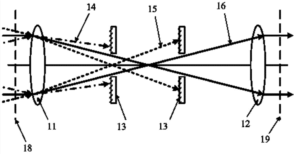
[0026] Such as figure 1 As shown, a spatial filter device provided by Embodiment 1 of the present invention includes a frequency division lens 11, a restoration lens 12, and at least two filter pinholes 13. The frequency division lens 11 and the restoration lens 12 constitute a confocal optical system, that is, The frequency lens 11 and the restoration lens 12 are arranged on the same optical axis, and the image focus of the frequency division lens 11 coincides with the object focus of the restoration lens 12; at least two filter apertures 13 are arranged on the focus of the confocal optical system and 11 and / or between the restoration lens 12, that is, at least two filter apertures 13 can be arranged between the focus of the confocal optical system and the frequency division lens 11, or both are arranged between the focus of the confocal optical system and the restoration lens 12 In between, one or more filter apertures 13 may also be provided on both sides of the focal point

Embodiment 2

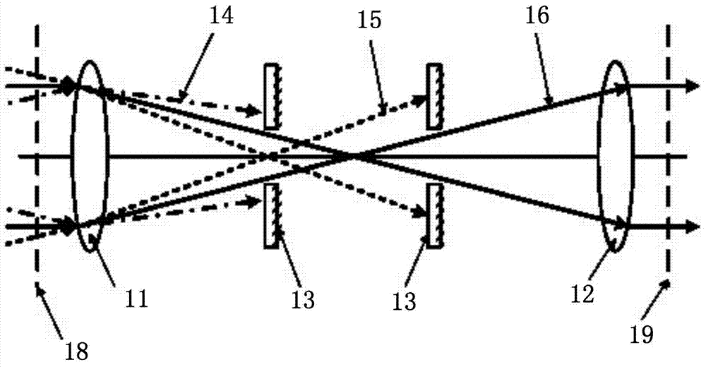
[0031] The spatial filtering device provided in Embodiment 2 is basically the same in structure as Embodiment 1, and the similarities will not be described again. The difference lies in:

[0032] Such as figure 2 As shown, in the direction of light propagation, the rear surface of the filter hole 13 is a textured surface, and the matrix material of the filter hole 13 is undoped yttrium aluminum garnet. At the front and rear positions of the focal point of the confocal optical system, the front and rear surfaces perpendicular to the incident laser beam are textured surfaces, and the different high-frequency components 14 in the incident laser beam are filtered by the surfaces of different filter pinholes 13 to achieve low-pass filter function.

Embodiment 3

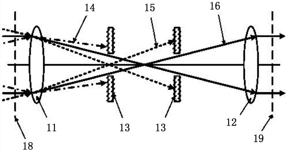
[0034] The spatial filtering device provided in the third embodiment has basically the same structure as that in the second embodiment, and the similarities will not be repeated, but the difference is:

[0035] Such as image 3 As shown, in the light propagation direction, the front and rear surfaces of the filter hole 13 are textured surfaces, and the matrix material of the filter hole 13 is sapphire. Located at the front and back of the focal point of the confocal optical system, the front and rear surfaces perpendicular to the laser incident are textured surfaces, relying on the double textured surface of different filter holes 13 to filter out different high-frequency components 14 in the incident laser beam, Realize the low-pass filter function.

[0036] In summary, the spatial filter device of the present invention uses the confocal frequency division lens 11 and the restoration lens 12 combined with different focal lengths, at least two filter holes 13 of low-absorption mat


PUM


Abstract

The invention relates to the technical field of spatial filtering devices, and provides a spatial filtering device. The spatial filtering device comprises a frequency division lens, a recovery lens and at least two filtering small holes, wherein the frequency division lens and the recovery lens form a confocal optical system; and the filtering small holes are positioned between a focal point of the confocal optical system and the frequency division lens and/or the recovery lens. The plurality of the filtering small holes share scattering effect of high-frequency components of a laser beam evenly, the laser power absorption of one single filtering small hole is reduced so that the safety performance is improved, and the filtering effect of various kinds of high-frequency components of the laser beam is significantly improved so that the low-pass spatial filtering function can be better realized. Since the filtering small holes are positioned far away from the focal point, the size of faculae is large, the corresponding power density is low, and spark phenomenon is not liable to occur. In addition, the size of the filtering small holes is large, the processing difficulty is reduced, the misalignment tolerance of small hole adjustment is increased, and the system is easy to operate stably.

Description


Claims


Application Information

Patent Timeline
Owner TECHNICAL INST OF PHYSICS & CHEMISTRY - CHINESE ACAD OF SCI
Why Eureka
Try Eureka