Movable micro-vibration squeeze compaction molding machine

A molding machine and shock pressing technology, applied in the field of sand casting, can solve the problems of inconvenient movement and transportation, complex structure and large volume, and achieve the effects of simple structure, small volume and low noise.

Inactive Publication Date: 2015-09-02
安庆旭东工贸有限责任公司
View PDF5 Cites 0 Cited by
  • Summary
  • Abstract
  • Description
  • Claims
  • Application Information

AI Technical Summary

Benefits of technology

This patented technology describes an improved vibrating compactor that can be used with boxes during manufacturing processes without taking up too much room or making it difficult to clean them afterwards after production. It also includes features like easy movement by adding a slide presser instead of a large lever arm, saving more space on top while still being effective at reducing sound levels compared to previous designs. Overall this design makes maintenance easier and efficient.

Problems solved by technology

Technics described in this patents are related to create strong structures from sand without adding extra materials or machining processes. However, current methods result in less accurate results due to imperfections such as cracks caused when filling the cavities between two parts together. To address these issues, there was developed a new method called Microspherie Compact Molding (MCS). MSC uses compressible fluid instead of traditional liquid foundations made of water glass mixed with other substances like calcium carbonates. By pressing down onto the bottom of the die plate while maintaining constant force applied through the suspension system, the entire mass becomes more rigid than before being pressed into shape. Additionally, the design allows for efficient movement over time because no separate movements take place. Overall, the technical problem addressed in this innovation is how to improve the strength and durability of sand cores formed within a compact tool while reducing their dimensions and weights.

Method used


Image

  • Movable micro-vibration squeeze compaction molding machine
  • Movable micro-vibration squeeze compaction molding machine
  • Movable micro-vibration squeeze compaction molding machine

Examples


Embodiment Construction

[0026] In order to make the technical means, creative features, goals and effects achieved by the present invention easy to understand, the present invention will be further described below in conjunction with specific illustrations.

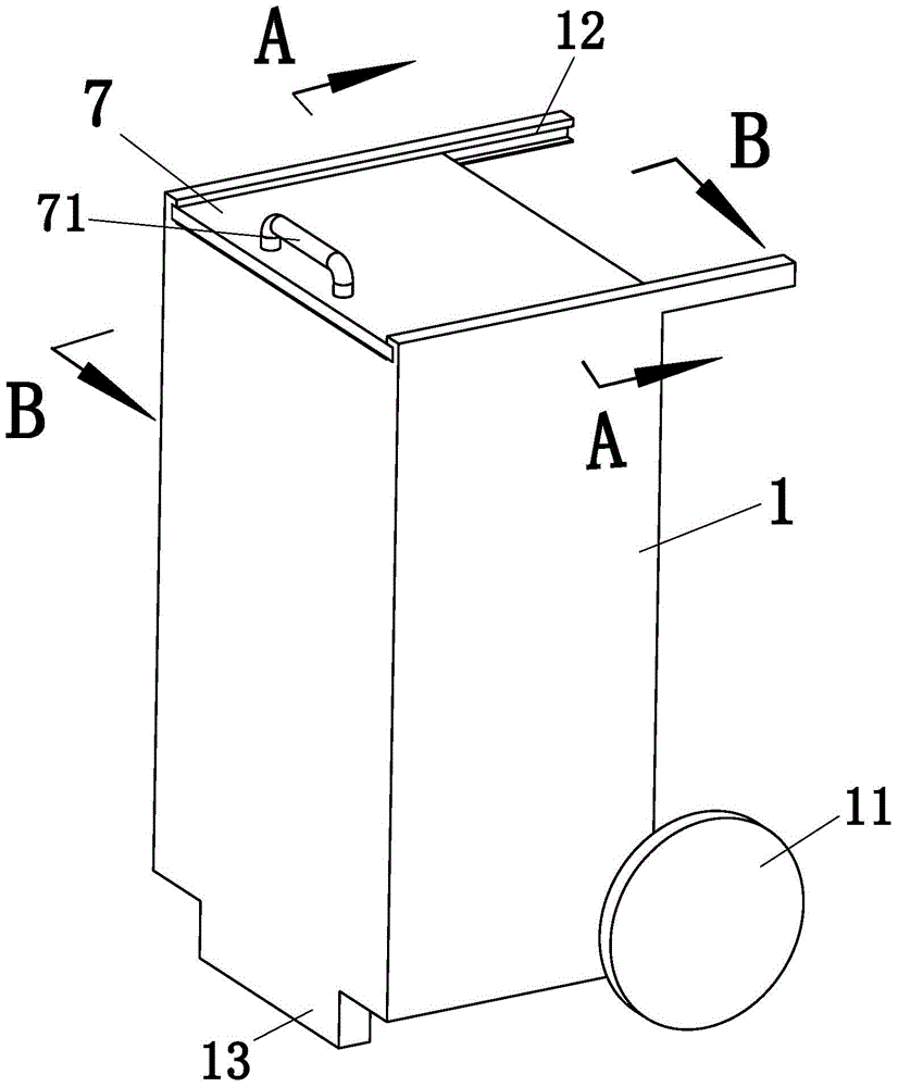
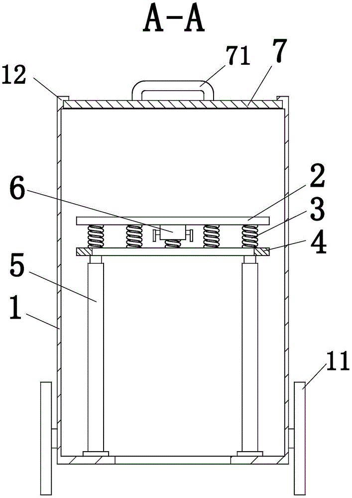
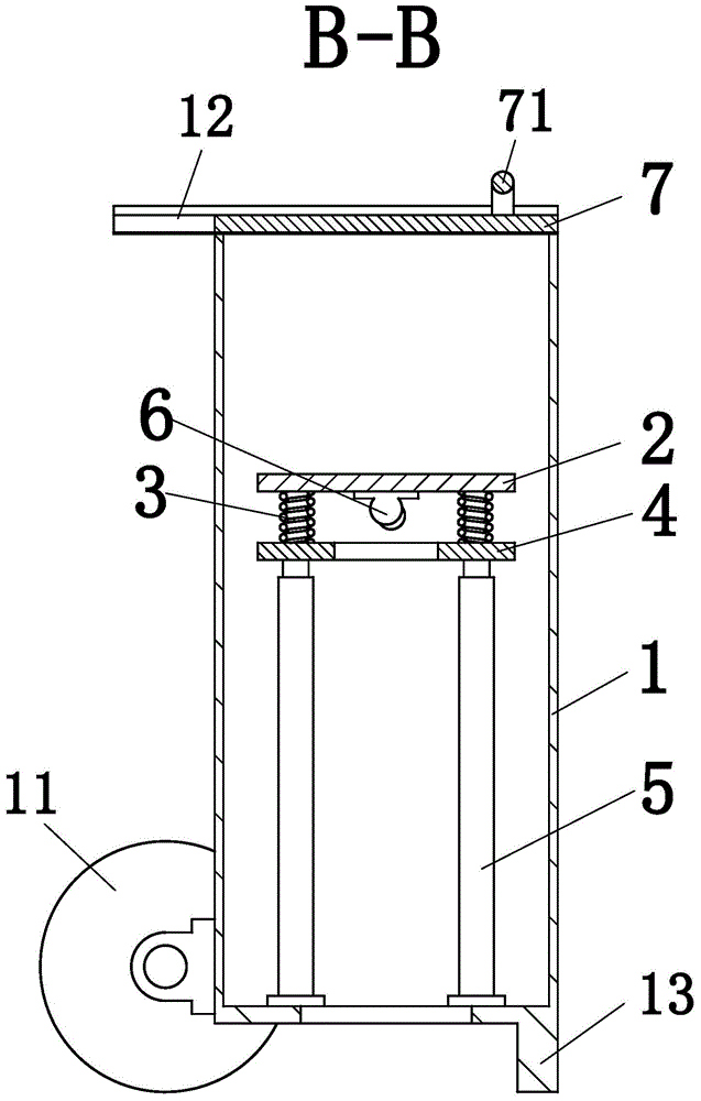
[0027] Such as Figure 1 to Figure 6 As shown, a movable microseismic compaction molding machine according to the present invention includes a body 1, a workbench 2, a spring 3, a linkage plate 4, a pneumatic cylinder 5, an eccentric motor 6 and a pressure plate 7. The body 1 A runner 11 is arranged at the rear and the bottom, and a slide rail 12 is arranged symmetrically on the center of the upper end surface of the body 1, and a chute is arranged on the slide rail 12; 3 are connected at one end, and the linkage plate 4 is connected with the other end of the spring 3; the four corners of the lower end surface of the linkage plate 4 are connected with four air cylinders 5, and the four air cylinders are fixed on the body 1, and the linkage plate 4


PUM


Abstract

The invention relates to the technical field of sand casting, and particularly relates to a movable micro-vibration squeeze compaction molding machine. The movable micro-vibration squeeze compaction molding machine comprises a machine body, an operating platform, a spring, a linkage plate, pneumatic cylinders, an eccentric motor and a pressing plate, wherein a rotating wheel is arranged at the rear lower part of the machine body, a sliding rail is symmetrically arranged at the left and right sides of the upper end surface of the machine body, and a sliding chute is formed in the sliding rail; the operating platform is horizontally positioned inside the machine body, the lower end surface of the operating platform is connected with one end of the spring, and the linkage plate is connected with the other end of the spring; four pneumatic cylinders are arranged at the four corners of the lower end surface of the linkage plate and are fixed on the machine body; the eccentric motor is installed at the lower end surface of the operating platform and is used for generating vibration; the pressing plate is positioned in the sliding chute, can slide in the sliding chute, and is used for compacting sand molds. The movable micro-vibration squeeze compaction molding machine can be used for slightly vibrating and compacting the sand molds, and has the characteristics of simple structure, light weight, convenience in movement and the like.

Description


Claims


Application Information

Patent Timeline
Owner 安庆旭东工贸有限责任公司
Why Eureka
Try Eureka