Novel centrifugal sand pump

A centrifugal and new type of technology, applied in the direction of non-variable pumps, non-displacement pumps, pumps, etc., can solve the problems of reducing the service life of centrifugal sand pumps, mud leakage, mud wear, etc., to solve the mud wear shaft seal and leakage problems, small footprint, and the effect of avoiding pollution

Inactive Publication Date: 2015-09-23
黄浩
View PDF5 Cites 1 Cited by
  • Summary
  • Abstract
  • Description
  • Claims
  • Application Information

AI Technical Summary

Benefits of technology

The technical effect that this innovation improves on existing designs for centrifuge systems. Its design includes an easy-to use machine without being affected by water or other liquids from its surroundings during operations. This results in less maintenance costs while still maintaining effective performance over time.

Problems solved by technology

The technical problem addressed by this patented technology relates to reducing damage caused from excessive use or misuse of centrally-pivoted vane impellers (centrifuge) due to poor lubrication conditions between them and causing contamination issues with environmental concerns such as soil erosion.

Method used


Image

  • Novel centrifugal sand pump

Examples


Embodiment Construction

[0010] The technical solutions in the embodiments of the present invention will be clearly and completely described below with reference to the accompanying drawings in the embodiments of the present invention. Obviously, the described embodiments are only a part of the embodiments of the present invention, but not all of the embodiments. Based on the embodiments of the present invention, all other embodiments obtained by those of ordinary skill in the art without creative efforts shall fall within the protection scope of the present invention.

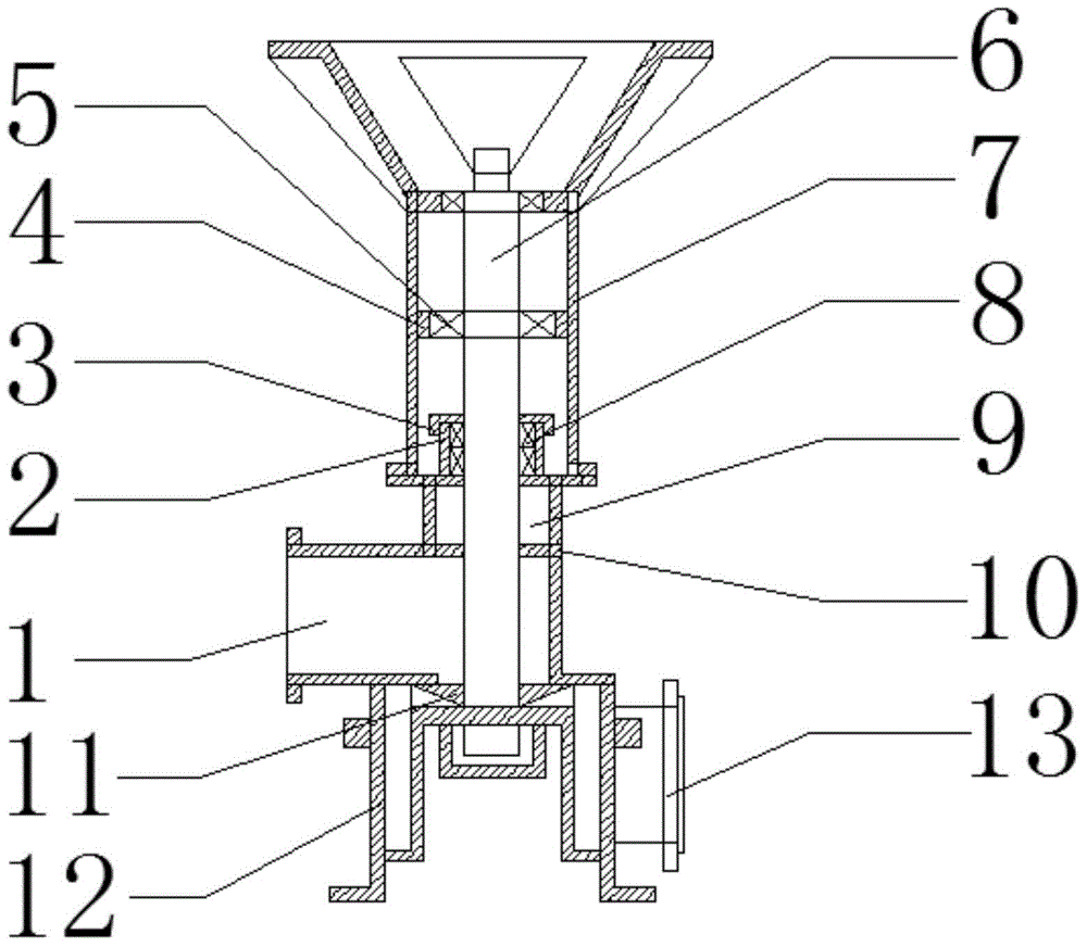
[0011] see figure 1 , The present invention provides a technical solution: a novel centrifugal sand pump, comprising a shaft seal gland 3, a bearing end cover 4, a pump shaft 6, a support body 7, an isolation cover 10, a pump wheel 11, and a pump casing 12, all of which are The pump shaft 6 is vertically arranged in the pump casing 12, the pump impeller 11 is connected with the lower end of the pump shaft 6, the pump impeller 11 is provi


PUM


Abstract

The invention discloses a novel centrifugal sand pump. A pump shaft is perpendicularly arranged inside a pump shell. A pump impeller is connected with the lower end of the pump shaft. The pump impeller is arranged inside the pump shell. The pump shell is connected with an isolation hood. The isolation hood is connected with a supporting body. A bearing is arranged between the pump shaft and the supporting body. The bearing is fixed through a bearing end cover. A packing box is arranged at the position where the isolation hood and the pump shaft are connected. An air chamber is arranged at the bottom of the packing box. A suction inlet is formed in the isolation hood. An outlet is formed in the right side of the pump shell. A shaft seal is arranged inside the packing box. The shaft seal is fixed through a shaft sealing pressing cover. The novel centrifugal sand pump is simple in structure, convenient to operate and small in occupied area, slurry and the packing box are isolated through the air chamber so that the slurry can make no contact with the shaft seal, the problems that the shaft seal is abraded by slurry and the slurry is leaked are solved fundamentally, the cost of replacing the shaft seal is saved, and pollution caused by slurry leakage to the environment is avoided.

Description


Claims


Application Information

Patent Timeline
Owner 黄浩
Why Eureka
Try Eureka