Rotary encoder

A rotary encoder, encoder technology, applied in electrical components, electrical switches, circuits, etc., to achieve the effect of miniaturization and low cost

Active Publication Date: 2015-11-25
MURATA MFG CO LTD
View PDF8 Cites 1 Cited by
  • Summary
  • Abstract
  • Description
  • Claims
  • Application Information

AI Technical Summary

Problems solved by technology

In this prior art, the convex portion formed on the movable contact piece elastically contacts the concave-convex surface provided on the case,

Method used


Image

  • Rotary encoder
  • Rotary encoder
  • Rotary encoder

Examples


Embodiment Construction

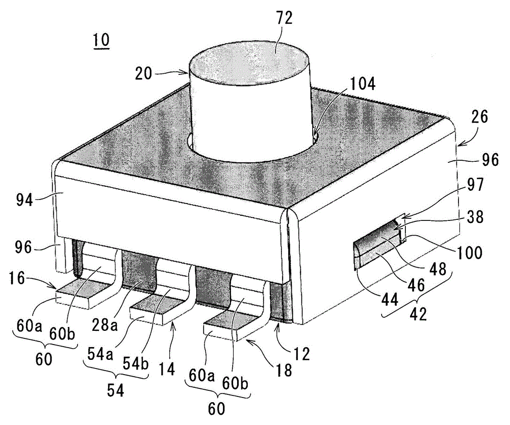
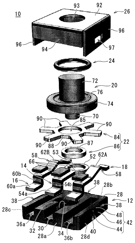
[0048] figure 1 It is a perspective view showing an example of an embodiment of the rotary encoder according to the present invention, figure 2 yes figure 1 exploded perspective view.

[0049] Such as figure 1 , figure 2 , Figure 11 , Figure 13 etc., for example, the rotary encoder 10 according to this embodiment mainly includes: a base member 12; a first fixed contact member 14 arranged on one main surface side of the base member 12; The second fixed contact members 16 and 18 on both sides of the fixed contact member 14; the rotor member 20 rotatably supported on one main surface side of the base member 12; The rotary contact member 22 in contact with the first fixed contact member 14; the compression member 24 arranged on the other end side in the axial direction of the rotor member 20; The rotary contact member 22 , the rotor member 20 , and the compression member 24 are attached to the cover member 26 of the base member 12 in a state of being sandwiched between the


PUM


Abstract

Provided is a rotary encoder allowing further size-reduction and cost-reduction to be achieved compared to prior art. The rotary encoder (10) comprises a base member (12), a first fixed contact member (14) provided on the base member (12), a plurality of second fixed contact members (16, 18) provided so as to leave a space to the first fixed contact member (14), a rotor member (20) rotatably supported by the base member (12), and a rotating contact member (22) having protruding and recessed portions in the rotation direction and rotating together with the rotor member (20). The first fixed contact member (14) is always in contact with the rotating contact member (22), and, through the rotation of the rotor member (20), the second fixed contact members (16, 18) become caught and released by the protruding and recessed portions of the rotating contact member (22), thereby bringing the rotating contact member (22) and the second fixed contact members (16, 18) into contact to turn the electrical connections between the rotating contact member (22) and the second fixed contact members (16, 18) on and off while giving rise to a clicking feel.

Description


Claims


Application Information

Patent Timeline
Owner MURATA MFG CO LTD
Why Eureka
Try Eureka