Multi-station bending device

A multi-station and equipment technology, applied in metal processing equipment, forming tools, manufacturing tools, etc.

Inactive Publication Date: 2016-01-20
SUZHOU FINTESTS MEASUREMENT & CONTROL TECH CO LTD
View PDF5 Cites 4 Cited by
  • Summary
  • Abstract
  • Description
  • Claims
  • Application Information

AI Technical Summary

Benefits of technology

This patented technology describes an apparatus used during manufacturing processes where electronics parts (such as semiconductor devices) are placed onto circuit boards or other carriers before being transferred between different stages within one machine. These machines have various tools like grippers, conveyors, and end-benders which work together with each stage's movements to transfer them safely without causing damage. By controlling these operations, the process becomes more efficient and accurate compared to previous methods requiring manual manipulation. Additionally, there may include features such as automatic loading/unloading of electronic part carrying cases when they reach their final destination. Overall, this innovation simplifies the overall production process while increasing productivity.

Problems solved by technology

In this patented technical problem addressed in that patents relates to improving the process of creating specific shapes or configurations with certain types of electronic component terminals during manufacturing. Current methods require manual loading and placement onto smaller modules which makes it hard to achieve these desired results without sacrifices accuracy.

Method used


Image

  • Multi-station bending device
  • Multi-station bending device
  • Multi-station bending device

Examples


Embodiment Construction

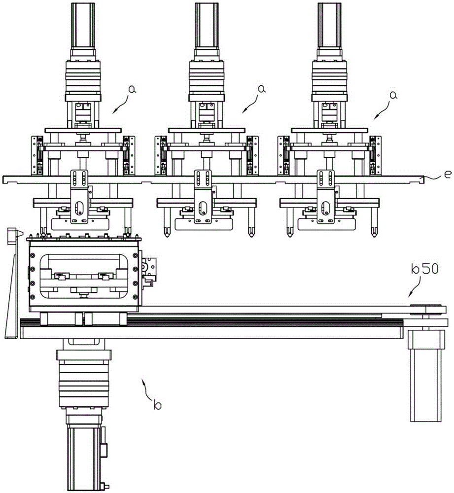
[0049] Such as figure 1 , a multi-station bending equipment, including a plurality of upper die mechanisms a and a lower die mechanism b; a plurality of upper die mechanisms are installed on a connecting plate e, and a lower die mechanism is installed on a forward and backward moving mechanism b50; Two upper mold mechanisms are arranged side by side laterally, and the front and rear moving mechanism drives the upper mold mechanism to move laterally.

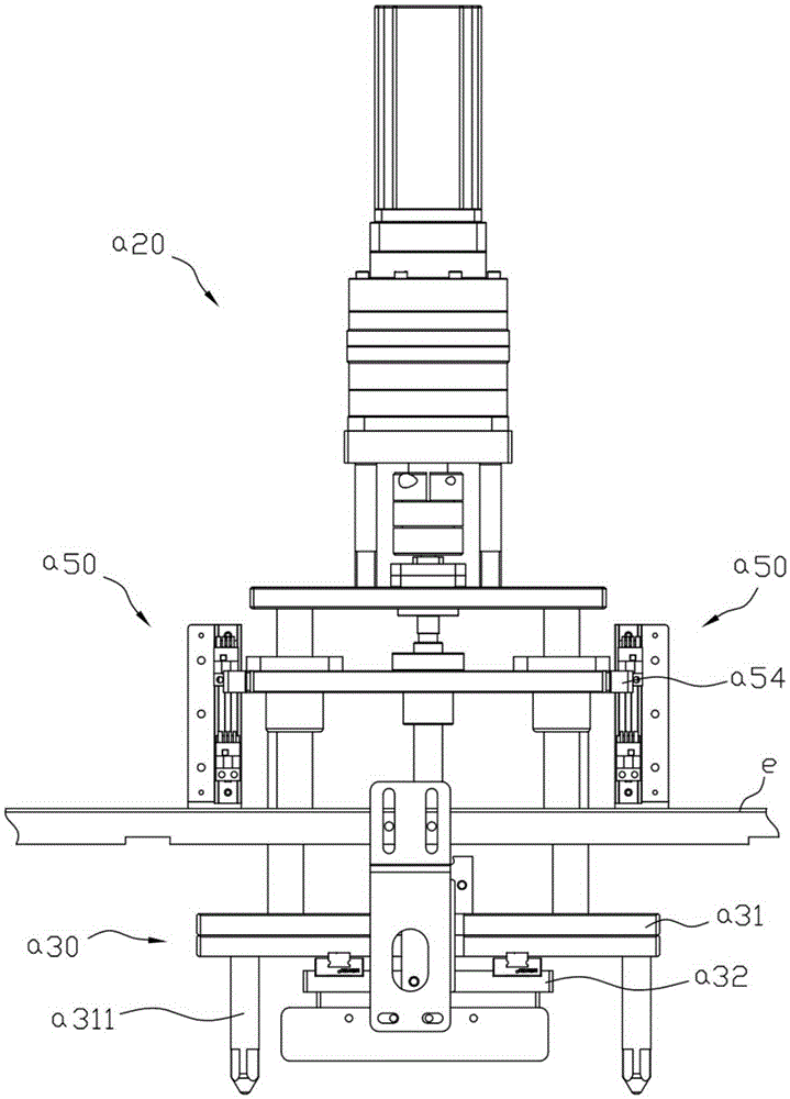
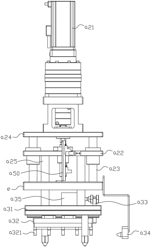
[0050] combine Figure 2 to Figure 4 Any upper mold mechanism in the above-mentioned multi-station bending equipment includes a lifting drive mechanism a20 installed on the connecting plate, a bending module a30 located below the connecting plate and connected to the lifting driving mechanism; the bending module includes The upper composite plate a31 and the bending module a32, the bottom of the upper composite plate is provided with a slide rail, the top of the bending module is provided with a chute matched with the slide rail, a


PUM


Abstract

The invention discloses a multi-station bending device. The multi-station bending device comprises a plurality of upper die mechanisms and a lower die mechanism. The multiple upper die mechanisms are arranged on a connecting plate. The lower die mechanism is arranged on a front-and-back moving mechanism. The multiple upper die mechanisms are transversely arranged in parallel. The front-and-back moving mechanism drives the lower die mechanism on the front-and-back moving mechanism to transversely move. The front-and-back moving mechanism drives the lower die mechanism to continuously move transversely to the position under the multiple upper die mechanisms transversely arranged. A preset shape is formed after N-time bending processing is carried out on terminals of electronic components through the multiple upper die mechanisms and the lower die mechanism. By means of the technical scheme, the preset complex shape can be achieved in the manner that the terminals of the batch of the electronic components loaded on the lower die mechanism are processed through the bending device.

Description


Claims


Application Information

Patent Timeline
Owner SUZHOU FINTESTS MEASUREMENT & CONTROL TECH CO LTD
Why Eureka
Try Eureka